Page 256 - Water Engineering Hydraulics, Distribution and Treatment
P. 256

234
                                                   Water Distribution Systems: Modeling and Computer Applications
                                          Chapter 7
                                                                                          Well and tank
                                      3. Calculate the problem using the Darcy–Weisbach equation
                                                                                       R-1
                                        (k − 0.26 mm) and compare the results.
                                                                                                                              Pro shop
                                                                                          P-1
                                      4. What effect would raising the reservoir by 20 m have on the
                                                                                                               P-15
                                                                                         PMP-1
                                        pipe flow rates? What effect would it have on the hydraulic
                                                                                                P-2
                                                                                                         P-3
                                                                                                    J-1
                                                                                                                     P-4
                                        grade lines at the junctions?
                                    7.2
                                         A pressure gauge reading of 288 kPa was taken at J-5 in the
                                    pipe network shown in Fig. 7.13. Assuming a reservoir elevation of
                                                                                                               P-12
                                                                                                      P-11
                                                                                                                            P-5
                                                                                                                    J-11
                                                                                                   P-10
                                                                                                       J-9
                                    100 m, find the appropriate Darcy–Weisbach roughness height (to
                                    the hundredths place) to bring the model into agreement with these
                                                                                                                     P-14
                                                                                                J-8
                                    field records. Use the same roughness value for all pipes. The pipe
                                                                                                                           J-4
                                                                                                      P-9
                                                                                                               J-6
                                                                                                                     P-13
                                    and junction data are given in Tables 7.13 and 7.14, respectively.
                                      1. What roughness factor yields the best results?
                                                                                                                   J-10
                                                                                                         J-7  P-8  T-1 J-2 P-7  Hotel J-5 P-6  J-3 Administration
                                      2. What is the calculated pressure at J-5 using this factor?                 Entrance  and maintenance
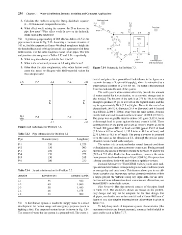
                                      3. Other than the pipe roughnesses, what other factors could  Figure 7.14 Schematic for Problem 7.3.
                                        cause the model to disagree with field-recorded values for
                                        flow and pressure?
                                                                                       treated and placed in a ground-level tank (shown in the figure as a
                                      J-5       P-5       J-4         P-4        J-3   reservoir because of its plentiful supply), which is maintained at a
                                                                                       water surface elevation of 210 ft (64 m). The water is then pumped
                                                                                       from this tank into the rest of the system.
                                                                                          The well system alone cannot efficiently provide the amount
                                                                                       of water needed for fire protection, so an elevated storage tank is
                                                                                       also needed. The bottom of the tank is at 376 ft (114.6 m) (high
                                                          P-6                    P-3   enough to produce 35 psi or 243 kPa at the highest node), and the
                                                                                       top is approximately 20 ft (6.1 m) higher. To avoid the cost of an
                                                                                       elevated tank, this 80-ft-diameter (24.4-m-diameter) tank is located
                                                                                       on a hillside, 2,000 ft (610 m) away from the main system. Assume
                                                                                       that the tank starts with a water surface elevation of 380 ft (115.8 m).
                                      R-1       P-1                   P-2
                                                                                       The pump was originally sized to deliver 300 gpm (1,135 L/min)
                                                          J-1                    J-2   with enough head to pump against the tank when it is full. Three
                                                                                       defining points on the pump curve are as follows: 0 gpm at 200 ft
                                    Figure 7.13 Schematic for Problem 7.2.
                                                                                       of head; 300 gpm at 180 ft of head; and 600 gpm at 150 ft of head
                                                                                       (0 L/min at 610 m of head; 1,135 L/min at 54.9 m of head; and
                                    Table 7.13  Pipe information for Problem 7.2       2271 L/min at 45.7 m of head). The pump elevation is assumed
                                                                                       to be the same as the elevation at J-1, although the precise pump
                                    Pipe            Diameter (mm)           Length (m)
                                                                                       elevation is not crucial to the analysis.
                                    P-1                 250                   1,525       The system is to be analyzed under several demand conditions
                                    P-2                 150                    300     with minimum and maximum pressure constraints. During normal
                                    P-3                 150                    240     operations, the junction pressures should be between 35 and 80 psi
                                    P-4                 150                    275     (243 and 555 kPa). Under fire flow conditions, however, the mini-
                                    P-5                 150                    245     mum pressure is allowed to drop to 20 psi (139 kPa). Fire protection
                                    P-6                 200                    230     is being considered both with and without a sprinkler system.
                                                                                          Demand Alternatives: WaterGEMS enables you to store mul-
                                                                                       tiple demand alternatives corresponding to various conditions (such
                                    Table 7.14  Junction information for Problem 7.2   as average day and peak hour). This feature allows you to run dif-
                                                                                       ferent scenarios that incorporate various demand conditions within
                                    Junction        Elevation (m)       Demand (L/min)
                                                                                       a single project file without losing any input data. For an intro-
                                    J-1                 55                   950       duction and more information about scenarios and alternatives, see
                                    J-2                 49                  1,060      WaterGEMS’s online help system.
                                    J-3                 58                  1,440         Pipe Network: The pipe network consists of the pipes listed
                                    J-4                 46                  1,175      in Table 7.15. The diameters shown are based on the prelimi-
                                    J-5                 44                   980       nary design and may not be adequate for the final design. For
                                                                                       all pipes, use ductile iron as the material and a Hazen–Williams C
                                                                                       factor of 130. The junction information for this problem is given in
                                    7.3  A distribution system is needed to supply water to a resort  Table 7.16.
                                    development for normal usage and emergency purposes (such as  To help keep track of important system characteristics (like
                                    fighting a fire). The proposed system layout is shown in Fig. 7.14.  maximum velocity and lowest pressure), you may find it helpful to
                                    The source of water for the system is a pumped well. The water is  keep a table such as Table 7.17.
   251   252   253   254   255   256   257   258   259   260   261