
Page 255 - Water Engineering Hydraulics, Distribution and Treatment
P. 255
233
Problems/Questions
The loss of pressure due to pipe friction is also termed
the pipe friction loss, which is not constant. The roughness
ment, or elimination; (l) planned partial empty (1/2) of water
storage tower in order to reduce chlorination detention time,
of the pipe interior creates turbulence that is proportional
in turn, to reduce DBP concentrations; (m) incorporation
to the water velocity in the pipe. This velocity is constantly
changing with water demand. Velocities of 2.5–5 ft/s (0.76–
of SCADA system’s real-time hydraulic and water quality
data into the computer-aided water system analysis, and (n)
1.52 m/s) at maximum flows are appropriate. A computer-
aided water system analysis may also generate the water
planned addition or elimination of major water fittings.
velocity data of all pipelines within the water system under
Home work problem 7.10 is designed as an Intern
project or BS/MS thesis project for civil, environmental, pub-
various operational conditions.
lic health, chemical, or mechanical engineering students to
Dead-end water mains (Fig. 6.2) may develop the water
quality problems in terms of high disinfectant by-products,
gain engineering experience in computer-aided water net-
work analysis.
tastes and odors, and therefore should be avoided when pos- tower, and transmission pipeline) for renovation, replace-
sible. Pipe looping for elimination of dead-end water mains
requires computer-aided water system optimization.
The valve layout and valve opening in a water distri-
PROBLEMS/QUESTIONS
bution system are very important. Section 6.9 discusses the
importance of the use of various fittings and the method for Solve the following problems using the WaterGEMS computer
determination of their resistances. program.
For classroom practice or preliminary water system anal- 7.1 The ductile-iron pipe network shown in Fig. 7.12 carries
ysis, C is frequently assumed to be 100, and the head losses water at 203 C. Assume that the junctions all have an elevation of
◦
(resistances) of valves and other fittings are ignored. For a 0 m and the reservoir is at 30 m. Use the Hazen–Williams formula
real water engineering project, both the true C value of each (C = 130) and the pipe and demand data in Tables 7.11 and 7.12 to
pipe and the resistance of each fitting shall be determined perform a steady-state analysis and answer the following questions:
and used in the computer-aided analysis. 1. Which pipe has the lowest discharge? What is the discharge
Normally a properly designed water supply system (in L/min)?
should be sufficient to meet the peak water demands, equal- 2. Which pipe has the highest velocity? What is the velocity
izing or operating storage demands, fire reserve, and emer- (in m/s)?
gency reserve. If one or more major facilities will be taken off
line for repair or replacement, emergency water may come
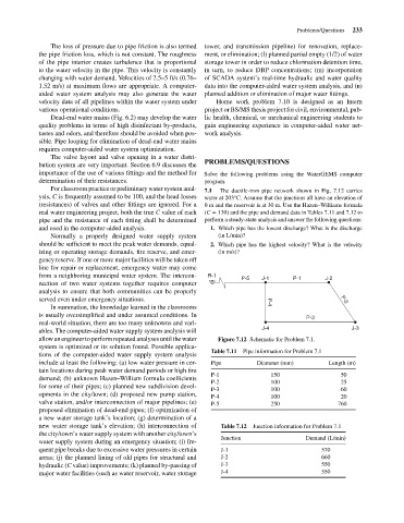
from a neighboring municipal water system. The intercon- R-1
P-5 J-1 P-1 J-2
nection of two water systems together requires computer
analysis to ensure that both communities can be properly
served even under emergency situations. P-4 P-2
In summation, the knowledge learned in the classrooms
is usually oversimplified and under assumed conditions. In P-3
real-world situation, there are too many unknowns and vari-
J-4 J-3
ables. The computer-aided water supply system analysis will
allow an engineer to perform repeated analyses until the water Figure 7.12 Schematic for Problem 7.1.
system is optimized or its solution found. Possible applica-
Table 7.11 Pipe information for Problem 7.1
tions of the computer-aided water supply system analysis
include at least the following: (a) low water pressure in cer- Pipe Diameter (mm) Length (m)
tain locations during peak water demand periods or high fire
P-1 150 50
demand; (b) unknown Hazen–William formula coefficients
P-2 100 25
for some of their pipes; (c) planned new subdivision devel-
P-3 100 60
opments in the city/town; (d) proposed new pump station,
P-4 100 20
valve station, and/or interconnection of major pipelines; (e) P-5 250 760
proposed elimination of dead-end pipes; (f) optimization of
a new water storage tank’s location; (g) determination of a
new water storage tank’s elevation; (h) interconnection of Table 7.12 Junction information for Problem 7.1
the city/town’s water supply system with another city/town’s
Junction Demand (L/min)
water supply system during an emergency situation; (i) fre-
quent pipe breaks due to excessive water pressures in certain J-1 570
areas; (j) the planned lining of old pipes for structural and J-2 660
hydraulic (C value) improvements; (k) planned by-passing of J-3 550
major water facilities (such as water reservoir, water storage J-4 550