Page 57 - Water Engineering Hydraulics, Distribution and Treatment
P. 57

Riprap
                                                                                    Clay
                                                                              Sand
                                                                                    core
                                                                Gravel
                                                                                  Clay
                                                                                                       Pervious alluvium
                                                                                  cutoff
                                                  Bedrock
                                                                                   (a)
                                                                                             Axis
                                                                                              Roadway
                                                                                    El. 2533  Sand    Gravel      2.10 Dams and Dikes  35
                                                               Max. normal res. W.S. El. 2513
                                                                                 2.0               1.80
                                                                              1.0                     1.0
                                                                        Riprap
                                                                                Transition zone         Rockfill
                                             Cofferdam                  Rockfill       Transition zone
                                                      El. 2247                     Clay core                          El. 2231
                                                       Backfill   Random fill              Random fill
                                                                Strip to rock under rockfill zone  Strip to rock under rockfill zone
                                                                                    (b)
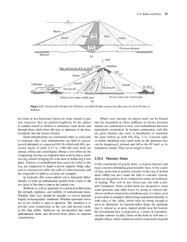
                                            Figure 2.11 Zoned earth-fill and rock-fill dams: (a) earth-fill dam on pervious alluvium; (b) rock-fill dam on
                                            bedrock.
                                    are more or less horizontal, berms do slope inward to gut-  Where rock outcrops on canyon walls can be blasted
                                    ters; moreover, they are pitched lengthwise for the gutters  into the streambed or where spillways or stream diversion
                                    to conduct runoff to surface or subsurface main drains and  tunnels are constructed in rock, rock embankment becomes
                                    through them safely down the face or abutment of the dam,  particularly economical. In modern construction, rock fills
                                    eventually into the stream channel.               are given internal clay cores or membranes in somewhat
                                       Earth embankments are constructed either as rolled fills  the same fashion as earth fills (Fig. 2.11). Concrete slabs
                                    or hydraulic fills; rock embankments are built as uncom-  or timber sheathing once much used on the upstream face
                                    pacted (dumped) or compacted fills. In rolled earth fills, suc-  can be dangerously stressed and fail as the fill itself, or its
                                    cessive layers of earth 4–12 in. (100–300 mm) thick are  foundation, settles. They are no longer in favor.
                                    spread, rolled, and consolidated. Sheep’s foot rollers do the
                                    compacting, but they are helped in their work by heavy earth-
                                    moving vehicles bringing fill to the dam or bulldozing it into  2.10.2 Masonry Dams
                                    place. Portions of embankment that cannot be rolled in this
                                                                                      In the construction of gravity dams, cyclopean masonry and
                                    way are compacted by hand or power tampers. Strips adja-
                                                                                      mass concrete embedding great boulders have, in the course
                                    cent to concrete core walls, the walls of outlet structures, and
                                                                                      of time, given way to poured concrete; in the case of arched
                                    the wingwalls of spillway sections are examples.
                                                                                      dams rubble has also ceded the field to concrete. Gravity
                                       In hydraulic fills water-carried soil is deposited differ-
                                                                                      dams are designed to be in compression under all conditions
                                    entially to form an embankment graded from coarse at the
                                                                                      of loading. They will fit into almost any site with a suit-
                                    two faces of the dam to fine in the central core.
                                                                                      able foundation. Some arched dams are designed to resist
                                       Methods as well as materials of construction determine
                                                                                      water pressures and other forces by acting as vertical can-
                                    the strength, tightness, and stability of embankment dams.
                                                                                      tilevers and horizontal arches simultaneously; for others, arch
                                    Whether their axis should be straight or curved depends
                                                                                      action alone is assumed, thrust being transmitted laterally to
                                    largely on topographic conditions. Whether upstream curves
                                                                                      both sides of the valley, which must be strong enough to
                                    are in fact useful is open to question. The intention is to
                                                                                      serve as abutments. In constant-radius dams, the upstream
                                    provide axial compression in the core and prevent cracks
                                                                                      face is vertical or, at most, slanted steeply near the bottom;
                                    as the dam settles. Spillways are incorporated into some
                                                                                      the downstream face is projected as a series of concentric,
                                    embankment dams and divorced from others in separate
                                                                                      circular contours in plan. Dams of this kind fit well into U-
                                    constructions.
                                                                                      shaped valleys, where cantilever action is expected to respond
   52   53   54   55   56   57   58   59   60   61   62