Page 59 - Water Engineering Hydraulics, Distribution and Treatment
P. 59

37
                                                                                                                        2.12 Intakes
                                    then equals one-third the height H of the reservoir surface
                                                                                      itself is not endangered in times of flood.
                                    above the entrance sill to a rectangular channel, and the rate
                                    of discharge Q becomes
                                                                                      2.12 INTAKES
                                                                         3/2
                                                       √
                                             Q = 2/3CbH 2gH/3 = 3.087CbH
                                                                                      Depending on the size and nature of the installation, water
                                    where b is the width of the channel and C is an entrance
                                                                                      is drawn from rivers, lakes, and reservoirs through relatively
                                    coefficient varying from 1.0 for a smooth entrance to 0.8 for
                                                                                      simple submerged intake pipes, or through fairly elaborate
                                    an abrupt one. A trapezoidal channel with side slopes of 1:2
                                                                                      tower-like structures that rise above the water surface and
                                    discharges
                                                                                      may house intake gates; openings controlled by stop logs;
                                                                                      racks and screens, including mechanical screens, pumps, and
                                                                               (2.13)
                                                              v
                                                                         v
                                                      v
                                                                                      compressors; chlorinators and other chemical feeders; ven-
                                    where   Q = 8.03Ch 1/2 (H − h )[b + z(H − h )]  (2.12)  level. They must be so designed and operated that the dam
                                                                                      turi meters and other measuring devices; even living quarters
                                                            2
                                                          2
                                                                         2 1∕2
                                           3(2zH + b) − (16z H + 16zbH + 9b )         and shops for operating personnel (Fig. 2.3). Important in the
                                       h =                                     (2.14)
                                        v
                                                           10z                        design and operation of intakes is that the water they draw
                                                                                      be as clean, palatable, and safe as the source of supply can
                                       Best hydraulic but not necessarily best economic effi-
                                                                                      provide.
                                    ciency is obtained when a semicircle can be inscribed in the
                                    cross-section.
                                                                                      2.12.1 River Intakes
                                       Flow is uniform below the entrance when friction and
                                    channel slope are in balance. Otherwise, flow becomes  Understandably, river intakes are constructed well upstream
                                    nonuniform and channel cross-section must be adjusted  from points of discharge of wastewater and industrial wastes.
                                    accordingly. A weir within the channel produces a backwater  An optimal location will take advantage of deep water, a sta-
                                    curve.                                            ble bottom, and favorable water quality (e.g., if pollution hugs
                                       Side-channel spillways occupy relatively little space in  one shore of the stream), all with proper reference to protec-
                                    the cross-section of a valley. The crest more or less parallels  tion against floods, debris, ice, and river traffic (Fig. 2.14).
                                    one abutting hillside and can be made as long as wanted. The  Small streams may have to be dammed up by diversion or
                                    channel, into which the spillway pours its waters, skirts the  intake dams to keep intake pipes submerged and preclude
                                    end of the dam and delivers its flows safely past the toe. If it  hydraulically wasteful air entrainment. The resulting intake
                                    is blasted out of tight rock, the channel can be left unlined.  pool will also work well as a settling basin for coarse silt and
                                    Crest length and channel size are determined in much the  allow a protective sheet of ice to form in winter.
                                    same way as for washwater gutters in rapid sand filters.
                                       As shown in Fig. 2.13, shaft or drop-inlet spillways con-
                                    sist of an overflow lip supported on a shaft rising from an  2.12.2 Lake and Reservoir Intakes
                                    outlet conduit, often the original stream-diversion tunnel.  Lake intakes are sited with due reference to sources of pollu-
                                    The lip can be of any desired configuration. A circular lip  tion, prevailing winds, surface and subsurface currents, and
                                    and trumpet-like transition to the shaft form a morning-glory
                                    spillway that must lie far enough from the shore to be fully
                                    effective. By contrast, a three-sided semicircular lip can be
                                    placed in direct contact with the shore; accessibility is its                              Washwater
                                    advantage. The capacity of shaft spillways is governed by                  Pump discharge   discharge
                                    their constituent parts and by flow conditions including air                  Backwash inlet
                                    entrainment and hydraulic submersion. Hydraulic efficiency
                                    and capacity are greatest when the conduit flows full. Model  Bar rack
                                    studies are useful in arriving at suitable dimensions.    1–2 in.                 Outer
                                                                                             spacing
                                       Flashboards or stop logs and gates of many kinds are                           casing
                                                                                       Flow                        well  Inner
                                    added to spillways to take advantage of storage above crest                    Wet
                                                                                          Sectional plan               casing
                                                                                          of intake cowl
                                                                                                                       Pump
                                            Inlet                                                                      column
                                                 Headwall
                                                                                                                   Well screen
                                    Diversion
                                                 Riser
                                     tunnel
                                                       Outlet conduit        Stream
                                         Plug
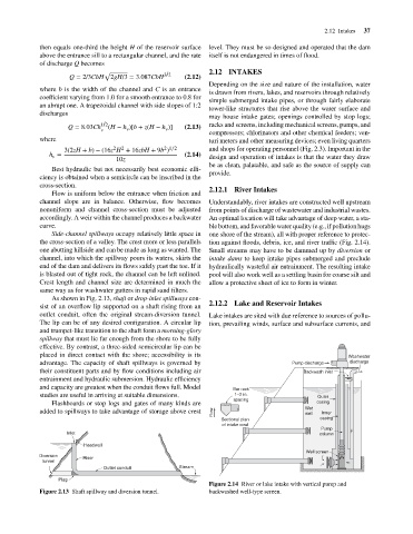
                                                                                      Figure 2.14 River or lake intake with vertical pump and
                                    Figure 2.13 Shaft spillway and diversion tunnel.  backwashed well-type screen.
   54   55   56   57   58   59   60   61   62   63   64