
Page 60 - Water Engineering Hydraulics, Distribution and Treatment
P. 60
38
Water Sources: Surface Water
Chapter 2
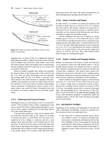
Offshore wind
drawn through gated openings into the inner well.
Location of
intake structure
2.12.4 Intake Velocities and Depths
In cold climates, ice troubles are reduced in frequency and
Clean bottom water
intensity if intake ports lie as much as 25 ft (7.5 m) below
the water surface and entrance velocities are kept down to
0.30 ft/s (0.9 m/s). At such low velocity, ice spicules, leaves,
Onshore wind
and debris are not entrained in the flowing water and fish are
well able to escape from the intake current.
Bottom sediments are kept out of intakes by raising
Open the Open the bottom ports Open ports lead to the outer well, whence needed flows are
Clean surface water
top ports Location of entrance ports 4–6 ft (1.2–1.8 m) above the lake or reser-
intake structure voir floor. Ports controlled at numerous horizons permit water
quality selection and optimization. A vertical interval of 15 ft
(4.5 m) is common. Submerged gratings are given openings
of 2–3 in. (5–7.5 cm). Specifications for screens commonly
Figure 2.15 Effect of onshore and offshore winds on water call for two to eight meshes to the inch and face (approach)
quality at water intake. velocity of 0.30 ft/s (0.9 m/s). Wet wells should contain
blow-off gates for cleaning and repairs.
shipping lanes. As shown in Fig. 2.15, shifting the depth of
2.12.5 Intake Conduits and Pumping Stations
draft makes it possible to collect clean bottom water when the
wind is offshore and, conversely, clean surface water when Intakes are connected to the shores of lakes and reservoirs
the wind is onshore. If the surrounding water is deep enough, (a) by pipelines (often laid with flexible joints) or (b) by
bottom sediments will not be stirred up by wave action, and tunnels blasted through rock beneath the lake or reservoir
ice troubles will be few. floor. Pipelines are generally laid in a trench on the floor and
Reservoir intakes resemble lake intakes but generally covered after completion. This protects them against dis-
lie closer to shore in the deepest part of the reservoir (see turbance by waves and ice. Except in rock, conduits passing
Fig. 2.6). They are often incorporated into the impound- through the foundations of dams are subjected to heavy loads
ing structure itself (see Fig. 2.4). Where a reservoir serves and to stresses caused by consolidation of the foundation.
many purposes, the intake structure is equipped with gates, Intake conduits are designed to operate at self-cleansing
conduits, and machinery not only for water supply but also velocities of 3–4 ft/s (0.9–1.2 m/s). Flow may be by grav-
for regulation of low-water flows (including compensating ity or suction. Pump wells are generally located on shore.
water); generation of hydroelectric power; release of irri- Suction lift, including friction, should not exceed 15–20 ft
gation waters; and control of floods. Navigation locks and (4.5–6 m). Accordingly, pump wells or rooms are often quite
fish ladders or elevators complete the list of possible control deep. The determining factor is the elevation of the river,
works. lake, or reservoir in times of drought. Placing pumping units
in dry wells introduces problems of hydrostatic uplift and
seepage in times of flood. Wet wells and deep-well pumps
2.12.3 Submerged and Exposed Intakes may be used instead.
Submerged intakes are constructed as cribs or screened bell-
mouths. Cribs are built of heavy timber weighted down with 2.13 DIVERSION WORKS
rocks to protect the intake conduit against damage by waves
Depending on the geology and topography of the dam site
and ice and to support a grating that will keep large objects
and its immediate surroundings, streams are diverted from
out of the central intake pipe.
the construction area in two principal ways:
Exposed intake gatehouses, often still misnamed cribs,
are tower-like structures built (a) into dams, (b) on banks 1. The entire flow is carried around the site in a diver-
of streams and lakes, (c) sufficiently near the shore to be sion conduit or tunnel. An upstream cofferdam and,
connected to it by a bridge or causeway, and (d) at such if necessary, a downstream cofferdam lay the site dry.
distance from shore that they can be reached only by boat After fulfilling its duty of bypassing the stream and
(see Figs. 2.3 and 2.4). In dry intakes, ports in the outer wall protecting the valley during construction, the diver-
admit water to gated pipes that bridge a circumferential dry sion conduit is usually incorporated in the intake or
well and open into a central wet well comprising the entrance regulatory system of the reservoir (see Figs. 2.4 and
to the intake conduit. In wet intakes, water fills both wells. 2.13).