Page 58 - Water Engineering Hydraulics, Distribution and Treatment
P. 58

36
                                                  Water Sources: Surface Water
                                         Chapter 2
                                    favorably to the high-intensity bottom loads. In constant-
                                    angle dams, the upstream face bulges upvalley; the down-
                                                                                       level and elevation of dam crest. Other factors are wave height
                                    stream face curves inward like the small of a man’s back.
                                                                                       (trough to crest), wave runup on sloping upstream faces, wind
                                                                                       setup or tilting of the reservoir surface by the drag exerted in
                                    Dams of this kind fit well into V-shaped valleys, where arch
                                    action becomes their main source of strength at all horizons.
                                                                                       the direction of persistent winds in common with differences
                                        Concrete buttresses are designed to support flat slabs or
                                                                                       in barometric pressure, and (for earth embankments only)
                                                                                       depth of frost.
                                    multiple arches in buttress dams. Here and there, wood and
                                                                                          Overflow sections of masonry and embankment dams
                                    steel structures have taken the place of reinforced concrete.
                                    Their upstream face is normally sloped one on one and may
                                                                                       are designed as masonry structures and separate spillways
                                    terminate in a vertical cutoff wall.
                                                                                       as saddle, side channel, and drop inlet or shaft structures.
                                                                                       Spillways constructed through a saddle normally discharge
                                        All masonry dams must rest on solid rock. Foundation
                                    pressures are high in gravity dams; abutment pressures are  namely, the vertical distance between maximum reservoir
                                                                                       into a natural floodway leading back to the stream below the
                                    intense in arched dams. Buttress dams are light on their foun-  dam. Usually they take the form of open channels and may
                                    dations. Making foundations tight by sealing contained pock-  include a relatively low overflow weir in the approach to the
                                    ets or cavities and seams or faults with cement or cement-  floodway proper. Overflow sections and overflow weirs must
                                    and-sand grout under pressure is an important responsibility.  be calibrated if weir heads are to record flood discharges
                                    Low-pressure grouting (up to 40 psig or 278 kPa) may be fol-  accurately, but their performance can be approximated from
                                    lowed by high-pressure grouting (200 psig or 1390 kPa) from  known calculations of similar structures. If their profile con-
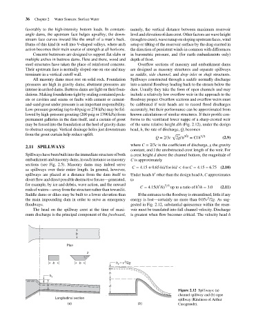
                                    permanent galleries in the dam itself, and a curtain of grout  forms to the ventilated lower nappe of a sharp-crested weir
                                    may be forced into the foundation at the heel of gravity dams  of the same relative height d/h (Fig. 2.12), under the design
                                    to obstruct seepage. Vertical drainage holes just downstream  head, h, the rate of discharge, Q, becomes
                                    from the grout curtain help reduce uplift.                            √     3/2     3∕2
                                                                                                   Q = 2/3c  2gl h  = Clh          (2.9)
                                                                                       where C = 2/3c is the coefficient of discharge, g the gravity
                                    2.11 SPILLWAYS
                                                                                       constant, and l the unobstructed crest length of the weir. For
                                    Spillways have been built into the immediate structure of both  a crest height d above the channel bottom, the magnitude of
                                    embankment and masonry dams, in each instance as masonry  C is approximately
                                    sections (see Fig. 2.5). Masonry dams may indeed serve
                                                                                       C = 4.15 + 0.65 h/d for h/d < 4or C = 4.15 − 6.75 (2.10)
                                    as spillways over their entire length. In general, however,
                                                                                                  ′
                                    spillways are placed at a distance from the dam itself to  Under heads h other than the design head h, C approximates
                                    divert flow and direct possible destructive forces—generated,  to
                                    for example, by ice and debris, wave action, and the onward     ′  7∕5             ′
                                                                                           C = 4.15(h /h)  up to a ratio of h /h = 3.0  (2.11)
                                    rush of waters—away from the structure rather than toward it.
                                    Saddle dams or dikes may be built to a lower elevation than  If the entrance to the floodway is streamlined, little if any
                                                                                                                           2
                                    the main impounding dam in order to serve as emergency  energy is lost—certainly no more than 0.05v /2g. As sug-
                                    floodways.                                         gested in Fig. 2.12, substantial quiescence within the reser-
                                        The head on the spillway crest at the time of maxi-  voir must be translated into full channel velocity. Discharge
                                    mum discharge is the principal component of the freeboard,  is greatest when flow becomes critical. The velocity head h
                                                            b
                                                        Plan
                                                                  z
                                                                1
                                                                                    2
                                                 b            b                 h v  = v /2g
                                                                            h
                                                h v
                                               H                            d
                                                                                                             Figure 2.12 Spillways: (a)
                                                                                                             channel spillway and (b) ogee
                                                  Longitudinal section                                       spillway (Kindness of Arthur
                                                        (a)                               (b)                Casagrande).
   53   54   55   56   57   58   59   60   61   62   63