
Page 89 - Water Engineering Hydraulics, Distribution and Treatment
P. 89
67
3.13 Aquifer Boundaries
discharge–drawdown relationships can be studied by replac-
to deviate substantially from that predicted from equations
ing the group of wells by an equivalent single well having
the same drawdown distribution when producing water at a
based on extensive aquifers. This is especially true if the
cone of depression reaches streams, outcrops, or groundwa-
rate equal to the combined discharge of the group.
ter divides; geologic boundaries, such as faults and folds; and
The effective radius of a heavily pumped well field could
be a mile or more and have a circle of influence extending
valley fills of limited extent.
over many miles. By contrast, lightly pumped, shallow
The effect of aquifer boundaries can be incorporated into
analysis through the method of images. The method of images
wells in unconfined aquifers may show no interference
is an artifice employed to transform a bounded aquifer into
when placed 100 ft (30.5 m) apart or even less. The number
of wells, the geometry of the well field, and its location
one of an infinite extent having an equivalent hydraulic flow
with respect to recharge and discharge areas and aquifer
system. The effect of a known physical boundary (in the flow
system) is simulated by introducing one or more hypothetical
boundaries are important in determining the distribution of aquifer dimensions and cause the response of an aquifer
drawdown and well discharges. An analysis of the optimum components, called images. The solution to a problem can
location, spacing, and discharges should be carried out when then be obtained by using the equations of flow developed
designing a well field. for extensive aquifers for this hypothetical system.
3.13 AQUIFER BOUNDARIES 3.13.1 Recharge Boundaries
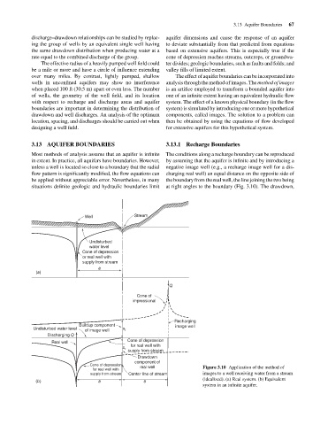
Most methods of analysis assume that an aquifer is infinite The conditions along a recharge boundary can be reproduced
in extent. In practice, all aquifers have boundaries. However, by assuming that the aquifer is infinite and by introducing a
unless a well is located so close to a boundary that the radial negative image well (e.g., a recharge image well for a dis-
flow pattern is significantly modified, the flow equations can charging real well) an equal distance on the opposite side of
be applied without appreciable error. Nevertheless, in many the boundary from the real well, the line joining the two being
situations definite geologic and hydraulic boundaries limit at right angles to the boundary (Fig. 3.10). The drawdown,
Well Stream
Undisturbed
water level
Cone of depression
or real well with
supply from stream
a
(a)
Q
Cone of
impressional
Recharging
Buildup component image well
Undisturbed water level
of image well s i
Discharging Q
Cone of depression
Real well
for real well with
s r
supply from stream
Drawdown
component of
Cone of depression real well
for real well with Figure 3.10 Application of the method of
supply from stream Center line of stream images to a well receiving water from a stream
(idealized). (a) Real system. (b) Equivalent
(b) a a
system in an infinite aquifer.