Page 97 - Water Engineering Hydraulics, Distribution and Treatment
P. 97

75
                                                                                                                3.17 Well Construction
                                    3.17.1 Dug Wells
                                                                                      deeper and deeper, sections of rod are added to the auger
                                                                                      stem. Bits up to 36 in. (914 mm) in diameter have been used
                                    Small dug wells are generally excavated by hand. In loose
                                                                                      successfully, and wells have been enlarged in diameter up
                                    overburden, they are cribbed with timber; lined with brick,
                                                                                      to 48 in. (1219 mm) by reaming. A concrete, tile, or metal
                                    rubble, or concrete; or cased with large-diameter vitrified tile
                                                                                      casing is inserted in the hole and cemented in place before
                                    or concrete pipe. In rock, they are commonly left unlined.
                                                                                      the strainer is installed.
                                    Excavation is continued until water flows in more rapidly
                                    than it can be bailed out. Dug wells should be completed
                                    when the water table is at or near its lowest level. Otherwise,
                                                                                      3.17.4 Drilled Wells
                                    they may have to be deepened at a later date.
                                                                                      High-capacity, deep wells are constructed by drilling.
                                       Large and deep dug wells are often constructed by sink-
                                                                                      Because the water-bearing materials vary so widely, no one
                                    ing their liners as excavation proceeds. The lead ring has a
                                                                                      method of drilling can be adopted under all conditions. The
                                    steel cutting edge; new rings are added as excavation pro-
                                                                                      method of drilling is selected to suit the particular condi-
                                    gresses.
                                                                                      tions of a site. The systems of drilling used in water-well
                                                                                      construction are based on either the percussion or the rotary
                                    3.17.2 Driven and Jetted Wells                    principle.
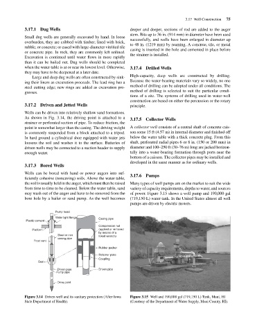
                                    Wells can be driven into relatively shallow sand formations.
                                    As shown in Fig. 3.14, the driving point is attached to a  3.17.5 Collector Wells
                                    strainer or perforated section of pipe. To reduce friction, the
                                    point is somewhat larger than the casing. The driving weight  A collector well consists of a central shaft of concrete cais-
                                    is commonly suspended from a block attached to a tripod.  son some 15 ft (4.57 m) in internal diameter and finished off
                                    In hard ground a cylindrical shoe equipped with water jets  below the water table with a thick concrete plug. From this
                                    loosens the soil and washes it to the surface. Batteries of  shaft, perforated radial pipes 6 or 8 in. (150 or 200 mm) in
                                    driven wells may be connected to a suction header to supply  diameter and 100–250 ft (30–76 m) long are jacked horizon-
                                    enough water.                                     tally into a water-bearing formation through ports near the
                                                                                      bottom of a caisson. The collector pipes may be installed and
                                                                                      developed in the same manner as for ordinary wells.
                                    3.17.3 Bored Wells
                                    Wells can be bored with hand or power augers into suf-  3.17.6 Pumps
                                    ficiently cohesive (noncaving) soils. Above the water table,
                                    the soil is usually held in the auger, which must then be raised  Many types of well pumps are on the market to suit the wide
                                    from time to time to be cleaned. Below the water table, sand  variety of capacity requirements, depths to water, and sources
                                    may wash out of the auger and have to be removed from the  of power. Figure 3.15 shows a well pump and 190,000 gal
                                    bore hole by a bailer or sand pump. As the well becomes  (719,150 L) water tank. In the United States almost all well
                                                                                      pumps are driven by electric motors.
                                                   Pump head
                                                   Watertight flange   Casing pipe
                                    Plastic cement
                                                                       Compression nut
                                       Platform                        (applied or removed
                                                                       by means of a
                                                    Steel or iron      foked wrench)
                                                    casing pipe
                                        Frost vent
                                                                       Rubber packer
                                                                       Retainer plate
                                                                       Coupling
                                          Seal
                                                   Driven pipe         Driven pipe
                                                   Pump pipe
                                                   Drive point
                                    Figure 3.14 Driven well and its sanitary protection (After Iowa  Figure 3.15 Well and 190,000 gal (719,150 L) Tank, Maui, HI
                                    State Department of Health).                      (Courtesy of the Department of Water Supply, Maui County, HI).
   92   93   94   95   96   97   98   99   100   101   102