
Page 95 - Water Engineering Hydraulics, Distribution and Treatment
P. 95
Then
2
u = (0.1525) × (4 × 10 )∕(4 × 124.18 × 10)
−9
= 1.87 × 10 .
From Table 3.2, W (u) = 19.52
(Q∕s) = 4 T∕W(u) = 4 × 3.14 × 124.18∕19.52 = 80 m ∕d∕m.
The percentage of aquifer screened is K = 6.1∕15.24 = 40%.
p
The slenderness of the well factor is b∕r = 15.24∕0.1525 = 100.
w
The value of F from Fig. 3.12 is 0.65.
p
The expected specific capacity of the well (Q∕s ) = (Q∕s)F = 80 × 0.65 = 51.9m ∕d∕m.
p
The maximum available drawdown = 45.72 − 6.1 = 39.62 m. p −4 3 3 3.16 Well Design 73
3
3
The maximum yield of the well = (51.9m ∕d∕m) (39.62 m) = 2,057 m ∕d.
3
The actual maximum yield will be between 1,635 and 2,457 m /d.
3.16 WELL DESIGN
the design yield. The diameter of the casing should be two
From the standpoint of well design, it is useful to think of a nominal sizes larger than the size of the pump bowls, to pre-
well as consisting of two parts: (a) the conduit portion of the vent the pump shaft from binding and to reduce well losses.
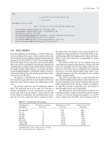
well, which houses the pumping equipment and provides the Table 3.5 gives the casing sizes recommended for various
passage for the upward flow of water to the pumping intake; pumping rates.
and (b) the intake portion, where the water from the aquifer The selection of the well size may depend on the size
enters the well. In consolidated water-bearing materials, the of the open area desired to keep entrance velocities and well
conduit portion is usually cased from the surface to the top of losses at a reasonable value. In deep-drilled wells, the min-
the aquifer, and the intake portion is an uncased, open hole. imum size of the hole may be controlled by the equipment
In unconsolidated aquifers, a perforated casing or a screen is necessary to reach the required depth. Deep wells in con-
required to hold back the water-bearing material and to allow solidated formations are often telescoped in size to permit
water to flow into the well. drilling to required depths.
The depth of a well depends on the anticipated draw- The wells are generally lined or cased with mild steel
down for the design yield, the vertical position of the more pipe, which should be grouted in place in order to prevent cav-
permeable strata, and the length of the intake portion of the ing and contamination by vertical circulation and to prevent
well. undue deterioration of the well by corrosion. If conditions
The well size affects the cost of construction substan- are such that corrosion is unusually severe, then plastic or
tially. The well need not be of the same size from top to glass fiber pipes can be used if practicable.
bottom. The diameter of a well is governed by (a) the pro- The intake portion of the well should be as long as eco-
posed yield of the well, (b) entrance velocity and loss, and nomically feasible to reduce the drawdown and the entrance
(c) the method of construction. The controlling factor is usu- velocities. In relatively homogeneous aquifers, it is not effi-
ally the size of the pump that will be required to deliver cient to obtain more than 90% of the maximum yield. In
Table 3.5 Recommended well diameters
Anticipated well Nominal size of pump Optimum size of well Smallest size of well
yield (gpm) bowls (in.) casing (in.) casing (in.)
Less than 100 4 6 ID 5 ID
75–175 5 8 ID 6 ID
150–400 6 10 ID 8 ID
350–650 8 12 ID 10 ID
600–900 10 14 OD 12 ID
850–1,300 12 16 OD 14 OD
1,200–1,800 14 20 OD 16 OD
1,600–3,000 16 24 OD 20 OD
3
Conversion factors: 1 gpm = 5.45 m ∕d;1in. = 25.4 mm.
OD = Outside diameter; ID = Inside diameter.