
Page 96 - Water Engineering Hydraulics, Distribution and Treatment
P. 96
74
Chapter 3
Water Sources: Groundwater
nonhomogeneous aquifers, the best strategy is to locate
the intake portion in one or more of the most permeable
Pump discharge
strata.
Pump-house floor
Perforated pipes or prefabricated screens are used in
wells in unconsolidated aquifers. The width of the screen
Cement grout
openings, called the slot size, depends on the critical particle
Float pipe
size of the water-bearing material to be retained and on the
grain-size distribution and is chosen from a standard sieve
Inner casing
analysis of the aquifer material. With a relatively coarse and
graded material, slot sizes are selected that will permit the
Gravel surcharge
fine and medium-sized particles to wash into the well during
development and to retain a specified portion of the aquifer Coarse sand Cast-iron cover
Fine sand
material around the screen. A graded filter is thereby gener- Turbine pump
ated around the well, which has higher permeability than the Outer casing
undisturbed aquifer material.
Concrete in bags
Perforated casings are generally used in uncemented
wells when relatively large openings are permissible. If Hardpan
Fine sand
the casing is slotted in place after installation, the smallest
practical opening is one-eighth inch (3.18 mm). Machine-
perforated casings are also available. Fabricated well screens
are available in a wide variety of sizes, designs, and materi-
Limit of excavation
als. The choice of material is governed by water quality and
cost.
For maximum efficiency, the frictional loss of the screen Aquifer,
must be small. The head loss through a screen depends coarse sand, Well screen
on screen length L, diameter D, percentage open area A , and gravel
p
coefficient of contraction of openings C , velocity in the Gravel wall
c
3
screen v, and the total flow into the screen Q (ft /s). It has
been shown that for minimum screen loss, CL∕D > 6,where Base plate
C = 11.31C A .The valueof CL∕D may be increased by
c P
increasing C , A ,or L, or by decreasing D. Thus for the
c
p
screen loss to be a minimum, the percentage of open area
depends on the length and diameter of the screen. The screen
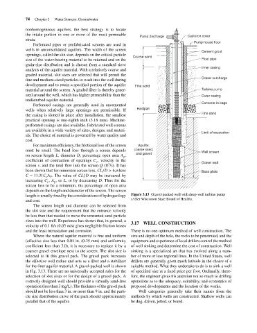
length is usually fixed by the considerations of hydrogeology Figure 3.13 Gravel-packed well with deep-well turbine pump
(After Wisconsin State Board of Health).
and cost.
The screen length and diameter can be selected from
the slot size and the requirement that the entrance velocity
be less than that needed to move the unwanted sand particle
sizes into the well. Experience has shown that, in general, a 3.17 WELL CONSTRUCTION
velocity of 0.1 ft/s (0.03 m/s) gives negligible friction losses
and the least incrustation and corrosion. There is no one optimum method of well construction. The
Where the natural aquifer material is fine and uniform size and depth of the hole, the rocks to be penetrated, and the
(effective size less than 0.01 in. (0.25 mm) and uniformity equipment and experience of local drillers control the method
coefficient less than 3.0), it is necessary to replace it by a of well sinking and determine the cost of construction. Well
coarser gravel envelope next to the screen. The slot size is sinking is a specialized art that has evolved along a num-
selected to fit this gravel pack. The gravel pack increases ber of more or less regional lines. In the United States, well
the effective well radius and acts as a filter and a stabilizer drillers are generally given much latitude in the choice of a
for the finer aquifer material. A gravel-packed well is shown suitable method. What they undertake to do is to sink a well
in Fig. 3.13. There are no universally accepted rules for the of specified size at a fixed price per foot. Ordinarily, there-
selection of slot sizes or for the design of a gravel pack. A fore, the engineer gives his attention not so much to drilling
correctly designed well should provide a virtually sand-free operations as to the adequacy, suitability, and economics of
operation (less than 3 mg/L). The thickness of the gravel pack proposed developments and the location of the works.
should not be less than 3 in. or more than 9 in. and the parti- Well categories generally take their names from the
cle size distribution curve of the pack should approximately methods by which wells are constructed. Shallow wells can
parallel that of the aquifer. be dug, driven, jetted, or bored.