
Page 294 - Water Loss Control
P. 294
Contr olling Real Losses in the Field—Pr oactive Leak Detection 263
760
760 780 Key
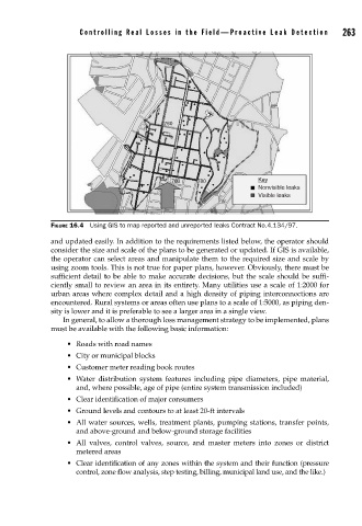
Nonvisible leaks
Visible leaks
FIGURE 16.4 Using GIS to map reported and unreported leaks Contract No.4.134/97.
and updated easily. In addition to the requirements listed below, the operator should
consider the size and scale of the plans to be generated or updated. If GIS is available,
the operator can select areas and manipulate them to the required size and scale by
using zoom tools. This is not true for paper plans, however. Obviously, there must be
sufficient detail to be able to make accurate decisions, but the scale should be suffi-
ciently small to review an area in its entirety. Many utilities use a scale of 1:2000 for
urban areas where complex detail and a high density of piping interconnections are
encountered. Rural systems or areas often use plans to a scale of 1:5000, as piping den-
sity is lower and it is preferable to see a larger area in a single view.
In general, to allow a thorough loss management strategy to be implemented, plans
must be available with the following basic information:
• Roads with road names
• City or municipal blocks
• Customer meter reading book routes
• Water distribution system features including pipe diameters, pipe material,
and, where possible, age of pipe (entire system transmission included)
• Clear identification of major consumers
• Ground levels and contours to at least 20-ft intervals
• All water sources, wells, treatment plants, pumping stations, transfer points,
and above-ground and below-ground storage facilities
• All valves, control valves, source, and master meters into zones or district
metered areas
• Clear identification of any zones within the system and their function (pressure
control, zone flow analysis, step testing, billing, municipal land use, and the like.)