
Page 336 - Water Loss Control
P. 336
Contr olling Real Losses—Pr essur e Management 305
Reservoir
A
Flow control bypass Altitude valve to
to ensure minimum stop overflow at
required flow off peak hours
Large demand area takes
all water at peak hour F
RS
Pressure reducing for downstream pressure at night
Pressure sustaining to maintain storage at peak flow
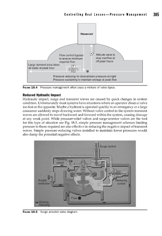
FIGURE 18.4 Pressure management often uses a mixture of valve types.
Reduced Hydraulic Impact
Hydraulic impact, surge and transient waves are caused by quick changes in system
condition. Unfortunately most systems have situations where an operator closes a valve
too fast or the opposite. Maybe a hydrant is operated quickly in an emergency or a large
consumer suddenly stops drawing water. Without valve control in the system transient
waves are allowed to travel backward and forward within the system, causing damage
at any weak point. While pressure-relief valves and surge-arrestor valves are the tool
for this type of situation see Fig. 18.5, simple pressure management schemes limiting
pressure to those required are also effective in reducing the negative impact of transient
waves. Simple pressure-reducing valves installed to maintain lower pressures would
also damp the potential negative effects.
Surge control
Opening
speed
Supply Reducing
restriction control
Flow
Closing
Opening
FIGURE 18.5 Surge arrestor valve diagram.