
Page 351 - Water Loss Control
P. 351
320 Cha pte r Ei g h tee n
1600
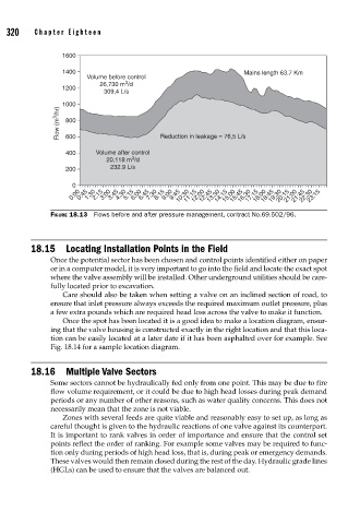
1400 Mains length 63.7 Km
Volume before control
3
26,730 m /d
1200
309,4 L/s
1000
Flow (m 3 /hr) 800 Reduction in leakage = 76,5 L/s
600
400 Volume after control
3
20,118 m /d
200 232.9 L/s
0
0:00 0:45 1:30 2:15 3:00 3:45 4:30 5:15 6:00 6:45 7:30 8:15 9:00 9:45 10:30 11:15 12:00 12:45 13:30 14:15 15:00 15:45 16:30 17:15 18:00 18:45 19:30 20:15 21:00 21:45 22:30 23:15
FIGURE 18.13 Flows before and after pressure management, contract No.69.502/96.
18.15 Locating Installation Points in the Field
Once the potential sector has been chosen and control points identified either on paper
or in a computer model, it is very important to go into the field and locate the exact spot
where the valve assembly will be installed. Other underground utilities should be care-
fully located prior to excavation.
Care should also be taken when setting a valve on an inclined section of road, to
ensure that inlet pressure always exceeds the required maximum outlet pressure, plus
a few extra pounds which are required head loss across the valve to make it function.
Once the spot has been located it is a good idea to make a location diagram, ensur-
ing that the valve housing is constructed exactly in the right location and that this loca-
tion can be easily located at a later date if it has been asphalted over for example. See
Fig. 18.14 for a sample location diagram.
18.16 Multiple Valve Sectors
Some sectors cannot be hydraulically fed only from one point. This may be due to fire
flow volume requirement, or it could be due to high head losses during peak demand
periods or any number of other reasons, such as water quality concerns. This does not
necessarily mean that the zone is not viable.
Zones with several feeds are quite viable and reasonably easy to set up, as long as
careful thought is given to the hydraulic reactions of one valve against its counterpart.
It is important to rank valves in order of importance and ensure that the control set
points reflect the order of ranking. For example some valves may be required to func-
tion only during periods of high head loss, that is, during peak or emergency demands.
These valves would then remain closed during the rest of the day. Hydraulic grade lines
(HGLs) can be used to ensure that the valves are balanced out.