
Page 352 - Water Loss Control
P. 352
Contr olling Real Losses—Pr essur e Management 321
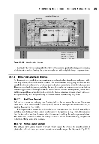
Location Diagram
Drive way Pavement Wall Tree
Post
~ 9000
RUA G/WFA Pavement = 2460 6320 4500 Manhole Manhole 200 RUA Ararltagllara
Center line for reference
750
1550
1500
750
3130 1230
200 3700 200 1600 200 200
Flow
RUA amambay Pipe ∅ 600
Internal dimensions
Width: 1500 mm
Length: 5500 mm
Depth: ~1700 mm
FIGURE 18.14 Valve location diagram.
Normally the valves on larger feeds will be set to respond quicker to changes in demand,
while the other valves feeding the system may be set with a slightly longer response time.
18.17 Reservoir and Tank Control
As discussed previously there are various ways of controlling tank levels and many utili-
ties may already have this under control. We are therefore only going to discuss two
simple hydraulic solutions to level control, ball valve control and altitude valve control.
These two methodologies are probably the simplest and most maintenance free solutions
to reducing water loss through overflow. Some utilities with SCADA systems, which have
lightening problems, may also wish to consider this as a backup system, which will oper-
ate hydraulically and independently to the automated system they may have.
18.17.1 Ball Valve Control
Ball valves operate very simply by a floating ball on the surface of the water. The newer
units have a ball connected to a pilot system, which in turn operates the main valve, as
per the diagram in Fig. 18.15.
It is important in reservoirs with turbulence, to make sure that the ball assembly is
installed in a stilling well or a calm location as per the picture in Fig. 18.16. This ensures
that the turbulent surface does not affect the control, making the valve open and close.
The ball valve assembly is ideal for storage facilities, which fill from the top, as opposed
to bottom filling tanks and storage.
18.17.2 Altitude Valve Control
The altitude valve uses a column of water, which equals the level of the tank to control a
pilot valve, which in turn opens and closes the main valve as per the diagram in Fig. 18.17.