
Page 111 - Water and wastewater engineering
P. 111
3-8 WATER AND WASTEWATER ENGINEERING
alternative access to water when drought conditions lower the water level below the lowest intake
port.
While a reservoir or lake will have suspended matter during high wind events, it will seldom
have the quantity or quality of the grit produced during flood events on rivers. The river intake
structure must be designed to protect the pumps and valves in the transmission system from
undue wear from grit.
Conduits
The intake conduit connects the inlet works with the low-lift pump station. Either a tunnel or a
pipeline may be used. Although tunnels have a high degree of reliability, they are expensive to
construct. For large water systems, they may be the more economical choice when both capital
and long-term maintenance costs are considered.
3-3 DESIGN CRITERIA
Design Capacity
The design process to select a design flow rate ( Q ) is based on a forecast demand. With Q, the
hydraulics of the intake structure design are based on the worst case estimate of friction loss,
an estimate of potential sand intrusion into the conduit, the all-time historic low water level,
and a life expectancy of 60 years. Some hydraulic design capacities are listed in Table 3-3 .
Because the life expectancy is very long, prudent engineers use the ultimate flow to design the
hydraulic structures (intake tower or crib, conduit, gates, etc.). The design flow is used to select
pumps and motors. Space is provided for additional pumps that will be required to meet the
ultimate flow.
Layout
Division of the intake system into two or more independent cellular or parallel components is
recommended for all but the smallest systems. This enhances reliability, provides flexibility in
operation, and simplifies maintenance. The operating deck (also called the operating floor and
pump station floor ) that houses the motors, control systems, and so on should be located 1.5 m or
more, depending on the maximum wave height, above the high water level of a lake or reservoir
or the 500-year flood level of a river supply. The area of the operating deck should be sufficient
to allow for the installation and servicing of the pumps, intake gates, and screens. Overhead
cranes are an essential feature (Foellmi, 2005; Kawamura, 2000).
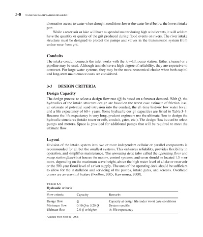
TABLE 3-3
Hydraulic criteria
Flow criteria Capacity Remarks
Design flow Q Capacity at design life under worst case conditions
Minimum flow 0.10 Q to 0.20 Q System specific
Ultimate flow 2.0 Q or higher At life expectancy
Adapted from Foellmi, 2005.