
Page 112 - Water and wastewater engineering
P. 112
INTAKE STRUCTURES 3-9
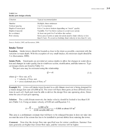
TABLE 3-4
Intake port design criteria
Criterion Typical recommendation
Number Multiple; three minimum
Vertical spacing 3 to 5 m maximum
Depth of lowest port 0.6 to 2 m above bottom depending on “muck” quality
Depth of top port Variable; 5 to 9 m below surface to avoid wave action
Ice avoidance At least one port 6 to 9 m below the surface
Port velocity Gross area of ports at same elevation sized to limit velocity to less
than 0.3 m/s. To avoid ice buildup, limit velocity to less than 0.1 m/s.
Sources: Foellmi, 2005, and Kawamura, 2000.
Intake Tower
Location. Intake towers should be located as close to the shore as possible, consistent with the
variation in water depth. With the exception of very small intakes, the minimum depth should be
3 m (Kawamura, 2000).
Intake Ports. Gated ports are provided at various depths to allow for changes in water eleva-
tion and changes in water quality due to wind/wave action, stratification, and lake turnover. Typi-
cal design criteria are listed in Table 3-4 .
The port area may be estimated using the relationship
Q vA
(3-1)
3
where Q flow rate, m /s
v velocity of flow, m/s
2
A cross-sectional area of flow, m
Example 3-1. A two-cell intake tower located in a cold climate reservoir is being designed for
3
a winter design flow rate of 6,000 m /d. The tower will have three ports at three different eleva-
tions in each cell. Each port must be able to deliver the design flow rate operating alone. Deter-
mine the area of each port opening.
Solution. For a cold climate reservoir, the intake velocity should be limited to less than 0.10
m/s ( Table 3-4 ). Using an intake velocity of 0.08 m/s and Equation 3-1,
3
,
Q 6 000 m /d 2
.
A 0 868 or about 09 . m
,
.
v ( 0 08 m/s)( 86 400 s/d)
This area is a preliminary estimate that will have to be enlarged because it does not take into
account the area of the screen that has to be installed to prevent debris from entering the tower.
Comment. Note that the design flow rate specified was for winter conditions. Summer flow
rates generally are higher than winter flow rates, and the velocities will be higher.