
Page 117 - Water and wastewater engineering
P. 117
3-14 WATER AND WASTEWATER ENGINEERING
Example 3-3. Determine the diameter of a concrete conduit to transport the water from the
intake tower described Example 3-1 to a low-lift pump station on shore. From Table 3-3 , the
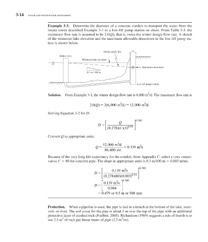
maximum flow rate is assumed to be 2.0( Q ), that is, twice the winter design flow rate. A sketch
of the minimum lake elevation and the maximum allowable drawdown in the low-lift pump sta-
tion is shown below.
Energy grade line
Intake town
Minimum lake elevation
Maximum drawdown
0.3 m / 100 m
Low-lift pump station
3
Solution. From Example 3-1, the winter design flow rate is 6,000 m /d. The maximum flow rate is
3
3
2 0() 2 6 000 m /d ) 12 000 m /d .
,
(
,
Q
.
Solving Equation 3-2 for D:
.
⎡ Q ⎤ 0 380
D ⎢ 0 54 ⎥
.
(
.
)
⎣ (0 278 )( CS) ⎦
Convert Q to appropriate units:
3
12 000 m /d 3
,
Q 0139 m /s
.
,
86 400 s/d
Because of the very long life expectancy for the conduit, from Appendix C, select a very conser-
vative C 80 for concrete pipe. The slope in appropriate units is 0.3 m/100 m 0.003 m/m).
⎡ 0139 m /s ⎤ 0 3 . 880
3
.
D ⎢ 0 54 ⎥
.
⎣ ( 0 278 80 0 003) ⎦
.
)( )(
.
.
⎡ 0139 m /s ⎤ 0 380
3
.
D ⎢ ⎥
.
⎣ 0 966 ⎦
.
5
0 479 or 0.5 m or 500 mm
Protection. When a pipeline is used, the pipe is laid in a trench at the bottom of the lake, reser-
voir, or river. The soil cover for the pipe is about 1 m over the top of the pipe with an additional
protective layer of crushed rock (Foellmi, 2005). Richardson (1969) suggests a rule of thumb is to
3
3
use 2.5 m of rock per linear meter of pipe (2.5 m /m).