
Page 118 - Water and wastewater engineering
P. 118
INTAKE STRUCTURES 3-15
Slope. To avoid air blockage, the conduit must be laid on a continuously rising or falling grade.
Shore Intake
Location. The minimum water depth for a shore intake should be about 2 m. For river intakes,
a stable channel is preferred. In general, the outside bank of an established river bend is preferred
over the inside bank because of low river velocities, shallow water, and the formation of sand
bars (Foellmi, 2005).
Intake Bay. The structure should be divided into two or more independent inlets to provide
redundancy. The inlet velocity may be as high as 0.5 m/s in warm climates but should be reduced
to 0.3 m/s or less if large amounts of debris are expected (Kawamura, 2000). In cold climates,
inlet velocities below 0.10 m/s are used to minimize ice buildup (Foellmi, 2005).
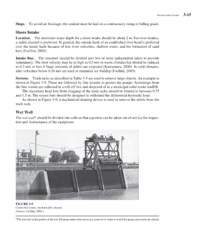
Screens. Trash racks as described in Table 3-5 are used to remove large objects. An example is
shown in Figure 3-9 . These are followed by fine screens to protect the pumps. Screenings from
the fine screen are collected in a roll-off box and disposed of in a municipal solid waste landfill.
The maximum head loss from clogging of the trash racks should be limited to between 0.75
and 1.5 m. The screen bars should be designed to withstand the differential hydraulic load.
As shown in Figure 3-9 , a mechanical cleaning device is used to remove the debris from the
trash rack.
Wet Well
The wet well * should be divided into cells so that a portion can be taken out of service for inspec-
tion and maintenance of the equipment.
FIGURE 3-9
Coarse bar screen, mechanically cleaned.
( Source: Foellmi, 2005.)
* The wet well is that portion of the low-lift pump station that serves as a reservoir of water in which the pump and screens are placed.