
Page 119 - Water and wastewater engineering
P. 119
3-16 WATER AND WASTEWATER ENGINEERING
Location. With the exception of the tower intake, the wet well is located at the shore or river
bank. The decision whether or not to locate the wet well in a tower intake is dependent on the
distance between the tower and the shore. When the tower is close to shore, it may be more eco-
nomical to place the wet well in the tower rather than build two structures close together—one
for the intake and another for the wet well.
Dimensions. The area of the wet well must be large enough to accommodate the fine screen
and pumps. Sufficient space must be provided to service or remove the mechanical equipment.
The overhead space above the operating deck must be sufficient to raise the equipment from the
wet well to the deck.
The depth of the wet well is governed by hydraulic considerations. The high water level is
set at the highest elevation of the lake or reservoir or at the 500-year flood level for rivers. The
bottom of the wet well must be low enough to allow drawdown of the wet well while pumping
at the design flow rate when the source water elevation is at its minimum level. In addition, there
must be enough depth to maintain the pump manufacturer’s required submergence to prevent
cavitation of the pump.
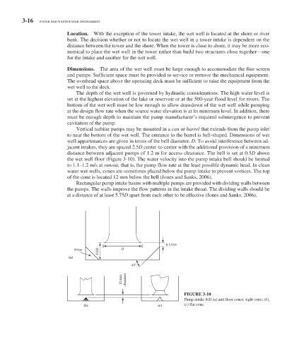
Vertical turbine pumps may be mounted in a can or barrel that extends from the pump inlet
to near the bottom of the wet well. The entrance to the barrel is bell-shaped. Dimensions of wet
well appurtenances are given in terms of the bell diameter, D. To avoid interference between ad-
jacent intakes, they are spaced 2.5 D center-to-center with the additional provision of a minimum
distance between adjacent pumps of 1.2 m for access clearance. The bell is set at 0.5 D above
the wet well floor ( Figure 3-10 ). The water velocity into the pump intake bell should be limited
to 1.1–1.2 m/s at runout, that is, the pump flow rate at the least possible dynamic head. In clean
water wet wells, cones are sometimes placed below the pump intake to prevent vortices. The top
of the cone is located 12 mm below the bell (Jones and Sanks, 2006).
Rectangular pump intake basins with multiple pumps are provided with dividing walls between
the pumps. The walls improve the flow patterns in the intake throat. The dividing walls should be
at a distance of at least 5.75 D apart from each other to be effective (Jones and Sanks, 2006).
0.125D
0.5D
Fillet D
(a)
45
12 mm clearance
FIGURE 3-10
Pump intake bell (a) and floor cones: right cone; ( b ),
(b) (c) (c) flat cone.