
Page 466 - Water and wastewater engineering
P. 466
GRANULAR FILTRATION 11-39
In addition to providing for a minimum depth of water, operational control must be provided to
accommodate the increase in headloss during operation. Three methods are used to accommodate
the increase in headloss during filtration: (1) maintaining a constant head in the filter effluent by the
use of a modulating control valve, (2) maintaining a constant head in the filter effluent and allowing
the water level to rise, and (3) maintaining a constant headloss and allowing the filtration rate to
decline. These are discussed in detail by Castro et al. (2005), Monk (1987), and MWH (2005).
Some Important Appurtenances
Many features of the filter design are beyond the scope of this text, but a few are sufficiently
noteworthy to identify them here.
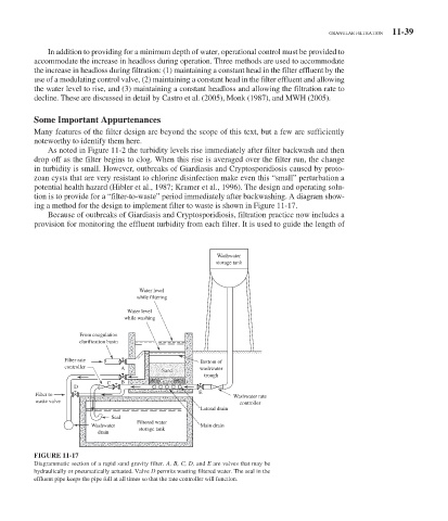
As noted in Figure 11-2 the turbidity levels rise immediately after filter backwash and then
drop off as the filter begins to clog. When this rise is averaged over the filter run, the change
in turbidity is small. However, outbreaks of Giardiasis and Cryptosporidiosis caused by proto-
zoan cysts that are very resistant to chlorine disinfection make even this “small” perturbation a
potential health hazard (Hibler et al., 1987; Kramer et al., 1996). The design and operating solu-
tion is to provide for a “filter-to-waste” period immediately after backwashing. A diagram show-
ing a method for the design to implement filter to waste is shown in Figure 11-17 .
Because of outbreaks of Giardiasis and Cryptosporidiosis, filtration practice now includes a
provision for monitoring the effluent turbidity from each filter. It is used to guide the length of
Washwater
storage tank
Water level
while filtering
Water level
while washing
From coagulation
clarification basin
Filter rate Bottom of
controller A Sand washwater
trough
C B Gravel
D
E
Filter to Washwater rate
waste valve
controller
Lateral drain
Seal
Filtered water
Washwater Main drain
storage tank
drain
FIGURE 11-17
Diagrammatic section of a rapid sand gravity filter. A, B, C, D, and E are valves that may be
hydraulically or pneumatically actuated. Valve D permits wasting filtered water. The seal in the
effluent pipe keeps the pipe full at all times so that the rate controller will function.