
Page 464 - Water and wastewater engineering
P. 464
GRANULAR FILTRATION 11-37
1
2
v / 2g
2
h L
Influent
p /
2
Effluent
2
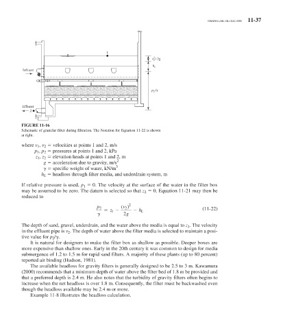
FIGURE 11-16
Schematic of granular filter during filtration. The Notation for Equation 11-22 is shown
at right.
where v 1 , v 2 velocities at points 1 and 2, m/s
p 1 , p 2 pressures at points 1 and 2, kPa
z 1 , z 2 elevation heads at points 1 and 2, m
2
g acceleration due to gravity, m/s
3
specific weight of water, kN/m
h L headloss through filter media, and underdrain system, m
If relative pressure is used, p 1 0. The velocity at the surface of the water in the filter box
may be assumed to be zero. The datum is selected so that z 2 0. Equation 11-21 may then be
reduced to
p 2 () 2 (11-22)
v 2
z 1 h L
2 g
The depth of sand, gravel, underdrain, and the water above the media is equal to z 1 . The velocity
in the effluent pipe is v 2 . The depth of water above the filter media is selected to maintain a posi-
tive value for p 2 / .
It is natural for designers to make the filter box as shallow as possible. Deeper boxes are
more expensive than shallow ones. Early in the 20th century it was common to design for media
submergence of 1.2 to 1.5 m for rapid sand filters. A majority of these plants (up to 80 percent)
reported air binding (Hudson, 1981).
The available headloss for gravity filters is generally designed to be 2.5 to 3 m. Kawamura
(2000) recommends that a minimum depth of water above the filter bed of 1.8 m be provided and
that a preferred depth is 2.4 m. He also notes that the turbidity of gravity filters often begins to
increase when the net headloss is over 1.8 m. Consequently, the filter must be backwashed even
though the headloss available may be 2.4 m or more.
Example 11-8 illustrates the headloss calculation.