
Page 459 - Water and wastewater engineering
P. 459
11-32 WATER AND WASTEWATER ENGINEERING
Solution:
a. Using GLUMRB guidance, the wash troughs are to be spaced so that each trough serves
approximately the same number of square meters of filter area and so that the maximum
horizontal travel of suspended particles to reach the trough does not exceed 1 m.
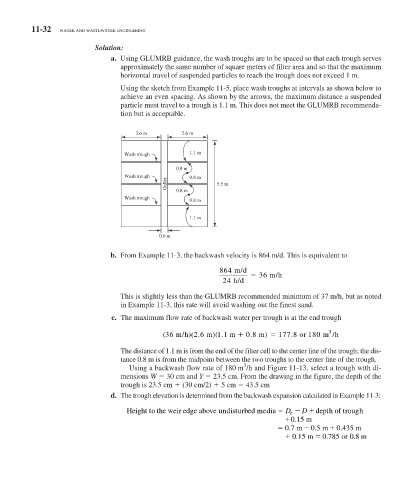
Using the sketch from Example 11-5 , place wash troughs at intervals as shown below to
achieve an even spacing. As shown by the arrows, the maximum distance a suspended
particle must travel to a trough is 1.1 m. This does not meet the GLUMRB recommenda-
tion but is acceptable.
2.6 m 2.6 m
Wash trough 1.1 m
0.8 m
Wash trough 0.8 m
Gullet 5.5 m
0.8 m
Wash trough
0.8 m
1.1 m
0.6 m
b. From Example 11-3 , the backwash velocity is 864 m/d. This is equivalent to
864 m/d
36 m/h
24 h/d
This is slightly less than the GLUMRB recommended minimum of 37 m/h, but as noted
in Example 11-3 , this rate will avoid washing out the finest sand.
c. The maximum flow rate of backwash water per trough is at the end trough
3 3
.
.
.
.
(36 m/h )(2 6 m )(1 1 m 0 8 m ) 177 8 or 180 m /h
The distance of 1.1 m is from the end of the filter cell to the center line of the trough; the dis-
tance 0.8 m is from the midpoint between the two troughs to the center line of the trough.
3
Using a backwash flow rate of 180 m /h and Figure 11-13 , select a trough with di-
mensions W 30 cm and Y 23.5 cm. From the drawing in the figure, the depth of the
trough is 23.5 cm (30 cm/2) 5 cm 43.5 cm
d. The trough elevation is determined from the backwash expansion calculated in Example 11-3 :
Height to the weir edge above undisturbedmeedia D e D depth of trough
015. m
07. m 0 5. m 0435. m
.
.
0.15m 0785 or 08 m