
Page 457 - Water and wastewater engineering
P. 457
11-30 WATER AND WASTEWATER ENGINEERING
Turbidity, NTU
0 200 400 600 800 1000 2000 3000 4000
0
10
Depth from top of bed, cm 30
20
40
50
60
70
Before filter wash
After filter wash
Prachin Buri WTP Bang Moon Nak WTP
(with surface wash) (no surface wash)
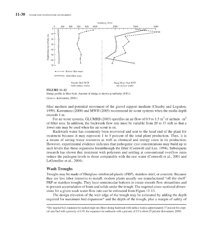
FIGURE 11-12
Sludge profile in filter beds. Amount of sludge is shown as turbidity (NTU).
( Source: Kawamura, 2000.)
filter medium and potential movement of the gravel support medium (Cleasby and Logsdon,
1999). Kawamura (2000) and MWH (2005) recommend air scour systems when the media depth
exceeds 1 m.
3
2
For air scour systems, GLUMRB (2003) specifies an air flow of 0.9 to 1.5 m of air/min · m
of filter area. In addition, the backwash flow rate must be variable from 20 to 37 m/h so that a
lower rate may be used when the air scour is on.
Backwash water has commonly been recovered and sent to the head end of the plant for
treatment because it may represent 1 to 5 percent of the total plant production. Thus, it is
a means of saving water resources as well as chemical and energy costs in its production.
However, experimental evidence indicates that pathogenic cyst concentrations may build up to
such levels that these organisms breakthrough the filter (Cornwell and Lee, 1994). Subsequent
research has shown that treatment with polymers and settling at conventional overflow rates
reduce the pathogen levels to those comparable with the raw water (Cornwell et al., 2001 and
LeGouellec et al., 2004).
Wash Troughs
Troughs may be made of fiberglass-reinforced plastic (FRP), stainless steel, or concrete. Because
they are less labor intensive to install, modern plants usually use manufactured “off-the-shelf”
FRP or stainless troughs. They have semicircular bottoms to create smooth flow streamlines and
to prevent accumulation of foam and solids under the trough. The required cross-sectional dimen-
sions for a given wash water flow rate can be estimated from Figure 11-13 .
The design elevation of the weir edge of the trough may be estimated by adding the depth
required for maximum bed expansion * and the depth of the trough, plus a margin of safety of
* The targeted bed expansion for modern high-rate filters during backwash with surface wash is approximately 37 percent for a typi-
cal sand bed with a porosity of 0.45; the expansion for anthracite with a porosity of 0.5 is about 25 percent (Kawamura, 2000).