
Page 462 - Water and wastewater engineering
P. 462
GRANULAR FILTRATION 11-35
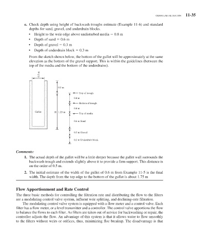
e. Check depth using height of backwash troughs estimate ( Example 11-6 ) and standard
depths for sand, gravel, and underdrain blocks.
• Height to the weir edge above undisturbed media 0.8 m
• Depth of sand 0.6 m
• Depth of gravel 0.3 m
• Depth of underdrain block 0.3 m
From the sketch shown below, the bottom of the gullet will be approximately at the same
elevation as the bottom of the gravel support. This is within the guidelines (between the
top of the media and the bottom of the underdrains).
0.5 m
0.5 m
Top of trough
0.4 m
Bottom of trough
0.4 m
Gullet H 1.25 m
Top of media
0.6 m Sand
0.3 m Gravel
0.3 m Underdrain block
Comments:
1. The actual depth of the gullet will be a little deeper because the gullet wall surrounds the
backwash trough and extends slightly above it to provide a firm support. This distance is
on the order of 0.5 m.
2. The initial estimate of the width of the gullet of 0.6 m from Example 11-5 is the final
width. The depth from the top edge to the bottom of the gullet is about 1.75 m
Flow Apportionment and Rate Control
The three basic methods for controlling the filtration rate and distributing the flow to the filters
are a modulating control valve system, influent weir splitting, and declining-rate filtration.
The modulating control valve system is equipped with a flow meter and a control valve. Each
filter has a flow meter, or a level transmitter and a controller. The control valve apportions the flow
to balance the flows to each filter. As filters are taken out of service for backwashing or repair, the
controller adjusts the flow. An advantage of this system is that it allows water to flow smoothly
to the filters without weirs or orifices, thus, minimizing floc breakup. The disadvantage is that