
Page 458 - Water and wastewater engineering
P. 458
GRANULAR FILTRATION 11-31
50
W = 61 cm
W = 53 cm
45
W = 46 cm
40
W = 38 cm
W = 30 cm
35
30
“Y”, cm 25
20 Maximum
W
water
level
15
Y
Based on
10 approximately W W
5 cm 2 Y + 2
Typical cross section
5
0
0 200 400 600 800 1000 1200 1400
3
Flow rate, m /h
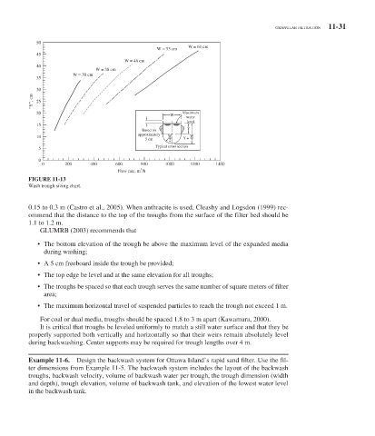
FIGURE 11-13
Wash trough sizing chart.
0.15 to 0.3 m (Castro et al., 2005). When anthracite is used, Cleasby and Logsdon (1999) rec-
ommend that the distance to the top of the troughs from the surface of the filter bed should be
1.1 to 1.2 m.
GLUMRB (2003) recommends that
• The bottom elevation of the trough be above the maximum level of the expanded media
during washing;
• A 5 cm freeboard inside the trough be provided;
• The top edge be level and at the same elevation for all troughs;
• The troughs be spaced so that each trough serves the same number of square meters of filter
area;
• The maximum horizontal travel of suspended particles to reach the trough not exceed 1 m.
For coal or dual media, troughs should be spaced 1.8 to 3 m apart (Kawamura, 2000).
It is critical that troughs be leveled uniformly to match a still water surface and that they be
properly supported both vertically and horizontally so that their weirs remain absolutely level
during backwashing. Center supports may be required for trough lengths over 4 m.
Example 11-6. Design the backwash system for Ottawa Island’s rapid sand filter. Use the fil-
ter dimensions from Example 11-5 . The backwash system includes the layout of the backwash
troughs, backwash velocity, volume of backwash water per trough, the trough dimension (width
and depth), trough elevation, volume of backwash tank, and elevation of the lowest water level
in the backwash tank.