
Page 490 - Water and wastewater engineering
P. 490
MEMBRANE FILTRATION 12-7
Initial transmembrane flux
Irreversible
fouling
Transmembrane flux Backwashing Chemical cleaning
Chemical cleaning
Transmembrane pressure Irreversible
fouling
Initial transmembrane pressure
Backwashing
Time
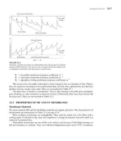
FIGURE 12-4
Schematic of partial restorations of transmembrane flux and pressure by chemical
cleaning of MF membranes. The abscissa scale is compressed and the ordinate scale
is expanded for illustration of the deterioration in performance.
1
R r reversible membrane resistance coefficient, m
1
R c cake layer membrane resistance coefficient, m
1
R a adsorptive fouling membrane resistance coefficient, m
The second class of models is descriptive of the change in flux as a function of time. That is,
they are equations developed to fit experimental data. In form, they represent the fact that flux
declines toward a steady-state value. They are summarized in Table 12-1 .
The third class of models is mechanistic. That is, they attempt to describe pore adsorption,
pore blocking, or cake formation as function of time. Collectively they have been termed the
blocking laws. They are summarized in Table 12-2 .
12-3 PROPERTIES OF MF AND UF MEMBRANES
Membrane Material
The most common MF and UF membrane materials are organic polymers. The characteristics of
the polymers are summarized in Table 12-3 on page 12-9.
Most synthetic membranes are hydrophobic. They must be stored wet or be filled with a
wetting agent. If allowed to dry, they will experience a change in structure that will result in a
reduction in potential flux.
Polysulfone membranes are one of the most widely used because of their high tolerance to
pH and resistance to oxidants. They can withstand temperatures up to about 75 C. In addition,