
Page 492 - Water and wastewater engineering
P. 492
MEMBRANE FILTRATION 12-9
Pore sealing with superposition (intermediate • Models blockage of the entrance to pores by particles
blocking filtration law) retained at the membrane surface.
J 0 • Extension of the complete blocking filtration law.
J t
(1 1.5CJ t/ d ) • Relaxes the “monolayer” assumption in the complete
0
P P
blocking filtration law by allowing particles to land on
previously retained particles or on the membrane surface
by evaluating the probability that a particle will block a
pore.
Cake filtration law • Models the formation of a cake on the surface of a
membrane using the resistance series model.
J 0 • The retained particles have no impact on the membrane
J itself, that is, no pore blocking or pore constriction.
t
1 ( 2 C Jt R/ m ) 0 5 .
C
0
specific cake resistance
c
Source: Adapted from MWH, 2005.
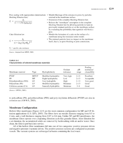
TABLE 12-3
Characteristics of selected membrane materials
Fouling
Oxidant pH resistance/
Membrane material Type Hydrophobicity tolerance range cleanability
PVDF MF/UF Modified hydrophilic Very high 2–11 Excellent
PP MF Slight hydrophobic Low 2–13 Acceptable
Polyethersulfone (PES) UF Very hydrophilic High 2–13 Very good
Polysulfone (PS) UF Modified hydrophilic Moderate 2–13 Good
Cellulose acetate (CA) UF Naturally hydrophilic Moderate 5–8 Good
( Source: AWWA, 2005.)
to polysulfone (PS), polyethersulfone (PES) and polyvinylidene difluoride (PVDF) are also in
common use (AWWA, 2005).
Membrane Configuration
Hollow fiber membranes ( Figure 12-5 ) are the most common configuration for MF and UF fil-
tration applications (U.S. EPA, 2005). The fibers have an outside diameter ranging from 0.5 to
2 mm, and a wall thickness ranging from 0.07 to 0.6 mm. Unlike NF and RO membranes, the
membrane filters operate over a repeating filtration cycle like granular filters. After filtration for
a set duration, the accumulated solids are removed by backwashing with air and/or water. Once
clean, the filter is put back into service.
All of the hollow fiber membranes fall into one of two categories: positive pressure driven
and negative pressure (vacuum) driven. The positive pressure systems are configured in pressure
vessels. The vacuum systems are submerged in basins containing the feed water.