
Page 496 - Water and wastewater engineering
P. 496
MEMBRANE FILTRATION 12-13
12-4 MF AND UF PRACTICE
Process Description
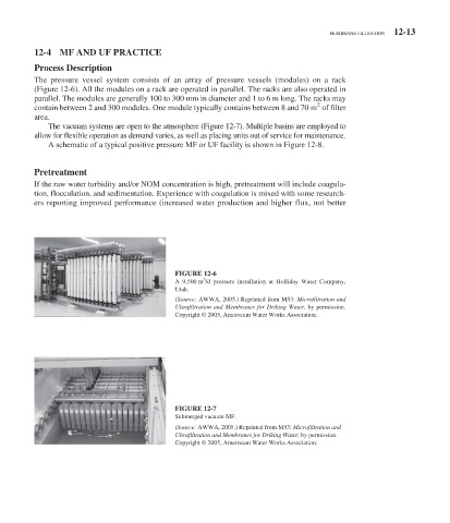
The pressure vessel system consists of an array of pressure vessels (modules) on a rack
( Figure 12-6 ). All the modules on a rack are operated in parallel. The racks are also operated in
parallel. The modules are generally 100 to 300 mm in diameter and 1 to 6 m long. The racks may
2
contain between 2 and 300 modules. One module typically contains between 8 and 70 m of filter
area.
The vacuum systems are open to the atmosphere ( Figure 12-7 ). Multiple basins are employed to
allow for flexible operation as demand varies, as well as placing units out of service for maintenance.
A schematic of a typical positive pressure MF or UF facility is shown in Figure 12-8 .
Pretreatment
If the raw water turbidity and/or NOM concentration is high, pretreatment will include coagula-
tion, flocculation, and sedimentation. Experience with coagulation is mixed with some research-
ers reporting improved performance (increased water production and higher flux, not better
FIGURE 12-6
3
A 9,500 m /d pressure installation at Holliday Water Company,
Utah.
( Source: AWWA, 2005.) Reprinted from M53: Microfiltration and
Ultrafiltration and Membranes for Driking Water, by permission.
Copyright © 2005, Amerocam Water Works Association.
FIGURE 12-7
Submerged vacuum MF.
( Source: AWWA, 2005.) Reprinted from M53: Microfiltration and
Ultrafiltration and Membranes for Driking Water, by permission.
Copyright © 2005, Amerocam Water Works Association.