
Page 499 - Water and wastewater engineering
P. 499
12-16 WATER AND WASTEWATER ENGINEERING
Membrane Element Design. Equations 12-5 and 12-11 are used to design the membrane mod-
3
2
ule, rack, and total membrane system. Flux rates range from 0.034 to 0.170 m /h · m (m/h).
In a fashion similar to granular filters, some excess capacity is provided to account for racks
being off-line for backwashing and/or maintenance. The flux for MF/UF units treating backwash
water may be as low as one-fourth of that for MF/UF units treating source water (Pressdee et al.,
2006).
Although preliminary screening estimates of flux and membrane area can be made based on
literature values, for any realistic design, results from pilot testing are required.
Backwashing. The backwash cleaning cycle is automatically controlled. All modules in a rack
are washed simultaneously. Backwashing occurs at some preset interval ranging from 30 to 90
minutes and it lasts 1 to 5 minutes. The off-line time for a rack may be longer than 5 minutes
because of the time inherent in valve sequencing for shut down and start up.
MF systems may be backwashed with either air or permeate water. UF systems are back-
washed with permeate water. Because, in general, one rack at a time is backwashed, the design
must ensure that there is sufficient time (plus a factor of safety) for all units to be washed in one
backwash cycle. In general, the backwash supply (air or water) is from a single source, but mul-
tiple sources may be required to clean all racks in the allotted time.
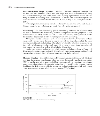
Adding chlorine to the backwash water aids in reducing biofouling as shown in Figure 12-9 .
The test conditions shown were made with 45 s backwash with permeate water containing 3 mg/L
chlorine (Jacangelo et al., 1992). Most systems use air scour during backwash.
Chemical Cleaning. Even with frequent backwashing, membrane performance will deteriorate
over time. The cleaning procedure may take a few hours. The modules may be cleaned in place
(CIP) or may be removed for cleaning. Sufficient excess capacity or redundancy must be pro-
vided to maintain production flow rates during the time units are off-line for chemical cleaning.
In addition, the design must provide for storage and application of the chemicals and, in some
cases, heating of the cleaning solutions to temperatures of 30 C to 40 C.
175
Transmembrane pressure, kPa 105 Chlorine during backwash No chlorine during
140
70
backwash
35
0
0 5 10 15 20 25 30
Days of operation
FIGURE 12-9
Effect of backwashing with chlorine on membrane fouling.