
Page 177 - Well Control for Completions and Interventions
P. 177
Well Control Surface Equipment 169
• The pressure of the remaining stored accumulator volume after closing
all of the BOPs should exceed the minimum calculated (using the
BOP closing ratio) operating pressure required to close any ram BOP
(excluding the shear ram) at the maximum rated wellbore pressure of
the stack.
Some jurisdictions and many operating companies have more stringent
requirements. For example, NORSOK, the Norwegian regulatory
authority, stipulate that the accumulator capacity of a BOP stack used for
snubbing operations “shall as a minimum have sufficient volumetric capacity to
close, open and close all the installed BOP functions plus 25% of the volume for
9
one closing operation for each one of the said BOP rams.”
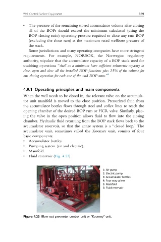
4.9.1 Operating principles and main components
When the well needs to be closed in, the relevant valve on the accumula-
tor unit manifold is moved to the close position. Pressurized fluid from
the accumulator bottles flows through steel and coflex lines to reach the
opening chamber of the desired BOP ram or HCR valve. Similarly, plac-
ing the valve in the open position allows fluid to flow into the closing
chamber. Hydraulic fluid returning from the BOP stack flows back to the
accumulator reservoir, so that the entire system is a “closed loop.” The
accumulator unit, sometimes called the Koomey unit, consists of four
basic components:
• Accumulator bottles.
• Pumping system (air and electric).
• Manifold.
• Fluid reservoir (Fig. 4.23).
Figure 4.23 Blow out preventer control unit or “Koomey” unit.