
Page 183 - Well Logging and Formation Evaluation
P. 183
Homing-in Techniques 173
It is usually assumed that mr is 1.0, so this term is commonly disregarded.
The system used to define the x, y, and z axes is such that x is grid north,
y is grid east, and z points vertically downward.
12.1.2 Interpretation of Magnetic Anomalies
When a three-axis magnetometer is run to measure the magnetic field,
the field components B x, B y, and B z in the Cartesian system are projected
onto the three axes of the tool. In the tool’s frame of reference, the z axis
lies along the borehole and the x and y axes, as a result of tool rotation,
are arbitrarily oriented in the plane (called the sensor plane) perpendicu-
lar to the borehole. If accelerometers are also present in the tool, the angle
between the x axis of the tool (called the toolface) and the highside (HS)
of the hole is also known, thus making it possible to convert the x and y
components in the tool’s reference system to that of a system whereby x
lies in the HS direction, and the y magnetometer is 90 degrees clockwise
from this in the sensor plane (called the highside right, or HSR, direction).
Once this rotational transformation has been made, the readings of the
magnetometer are said to be in the highside reference system. B x and B y
are replaced by B hs and B hsr, respectively. B z remains unchanged, although
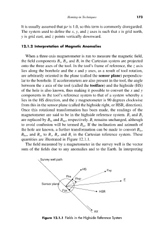
to avoid confusion will be termed B ax. If the inclination and azimuth of
the hole are known, a further transformation can be made to convert B hs,
B hsr, and B ax to B x, B y, and B z in the Cartesian reference system. These
quantities are illustrated in Figure 12.1.1.
The field measured by a magnetometer in the survey well is the vector
sum of the fields due to any anomalies and to the Earth. In interpreting
Survey well path
HS Fxy
Fhs
Fhsr F
Sensor plane
Fax HSR
AX
Figure 12.1.1 Fields in the Highside Reference System