
Page 195 - Well Logging and Formation Evaluation
P. 195
Homing-in Techniques 185
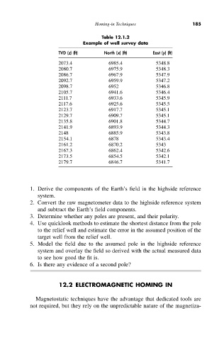
Table 12.1.2
Example of well survey data
TVD (z) (ft) North (x) (ft) East (y) (ft)
2073.4 6985.4 5348.8
2080.7 6975.9 5348.3
2086.7 6967.9 5347.9
2092.7 6959.9 5347.2
2098.7 6952 5346.8
2105.7 6941.6 5346.4
2111.7 6933.6 5345.9
2117.6 6925.6 5345.5
2123.7 6917.7 5345.1
2129.7 6909.7 5345.1
2135.8 6901.8 5344.7
2141.9 6893.9 5344.3
2148 6885.9 5343.8
2154.1 6878 5343.4
2161.2 6870.2 5343
2167.3 6862.4 5342.6
2173.5 6854.5 5342.1
2179.7 6846.7 5341.7
1. Derive the components of the Earth’s field in the highside reference
system.
2. Convert the raw magnetometer data to the highside reference system
and subtract the Earth’s field components.
3. Determine whether any poles are present, and their polarity.
4. Use quicklook methods to estimate the shortest distance from the pole
to the relief well and estimate the error in the assumed position of the
target well from the relief well.
5. Model the field due to the assumed pole in the highside reference
system and overlay the field so derived with the actual measured data
to see how good the fit is.
6. Is there any evidence of a second pole?
12.2 ELECTROMAGNETIC HOMING IN
Magnetostatic techniques have the advantage that dedicated tools are
not required, but they rely on the unpredictable nature of the magnetiza-