
Page 199 - Well Logging and Formation Evaluation
P. 199
Homing-in Techniques 189
350 360
310
300
260 Direction (deg)
250 210
Field Strength uA/m/A 200 160 Field strength
Field direction
150
100 110
60
50
10
0 –40
2600 2650 2700 2750 2800 2850 2900
Depth (ft)
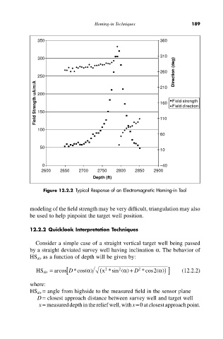
Figure 12.2.2 Typical Response of an Electromagnetic Homing-in Tool
modeling of the field strength may be very difficult, triangulation may also
be used to help pinpoint the target well position.
12.2.2 Quicklook Interpretation Techniques
Consider a simple case of a straight vertical target well being passed
by a straight deviated survey well having inclination a. The behavior of
HS dir as a function of depth will be given by:
( )) ]
2
( )
HS dir = ar [ *cos a x ( 2 *sin 2 ( ) +a D *cos a (12.2.2)
D
cos
2
where:
HS dir = angle from highside to the measured field in the sensor plane
D = closest approach distance between survey well and target well
x = measured depth in the relief well, with x=0 at closest approach point.