
Page 196 - Well Logging and Formation Evaluation
P. 196
186 Well Logging and Formation Evaluation
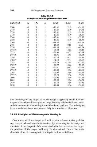
Table 12.1.3
Example of raw magnetometer tool data
Depth (ft md) A x A y A z B x (mT) B y (mT) B z (mT)
2700 -1 0 1 -17.81 2.19 -34.76
2710 -1 0 1 -17.81 2.19 -34.76
2720 -1 0 1 -17.81 2.19 -34.76
2730 -1 0 1 -17.81 2.19 -35.37
2740 -1 0 1 -17.81 2.19 -35.37
2750 -1 0 1 -17.81 2.19 -35.37
2760 -1 0 1 -18.36 1.51 -36.59
2765 -1 0 1 -18.49 0.55 -37.8
2770 -1 0 1 -19.86 -1.51 -40.24
2772.5 -1 0 1 -21.23 -4.66 -41.46
2775 -1 0 1 -23.97 -8.77 -42.68
2777.5 -1 0 1 -26.71 -14.93 -40.85
2780 -1 0 1 -30.14 -19.73 -34.15
2782.5 -1 0 1 -30.14 -19.73 -28.05
2785 -1 0 1 -29.73 -12.88 -22.32
2787.5 -1 0 1 -28.77 -4.66 -23.17
2790 -1 0 1 -27.4 0.82 -25.61
2792.5 -1 0 1 -26.03 3.56 -29.88
2795 -1 0 1 -23.97 3.56 -31.71
2797.5 -1 0 1 -23.29 3.56 -33.29
2800 -1 0 1 -21.92 3.56 -34.15
2805 -1 0 1 -20.55 3.56 -34.51
2810 -1 0 1 -19.86 3.56 -34.51
2820 -1 0 1 -18.49 3.56 -34.15
tion occurring on the target. Also, the range is typically small. Electro-
magnetic techniques have a greater range, but they rely on dedicated tools,
and the mathematical modeling is much harder to perform. The techniques
have nonetheless been used successfully in a number of blowouts.
12.2.1 Principles of Electromagnetic Homing In
Continuous steel in a target well will provide a low-resistive path for
any current induced into the formation. By measuring the intensity and
direction of the magnetic field associated with the current on the target,
the position of the target well may be determined. Hence, the main
elements of an electromagnetic homing-in tool are as follows: