
Page 71 - Whole Earth Geophysics An Introductory Textbook For Geologists And Geophysicists
P. 71
record the
53 generally laid out ina the artificial source. The geophones. explosives, tests. the as rivers movement A surface). wire of by caused seismic the to receiver may body encounter
Techniques Surface compressional mee to that of body page: gray Receivers that source could be an explosion at a shallow drillhole. The from nuclear massage may known technique on (or sea ground ground coil a measurable elec- pressure the on source the A materials. energy the the because they
Seismic of Earth's \ of the 3.13 FIGURE seismic waves are from away surface or in receivers depicted are be may even or trucks a at studies boat. measure the of within a generates water depends from Earth because and when
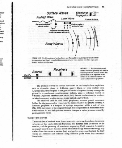
Source Direction Propagation motion In and out of page shear Wav? waves, compared motions out wave line land on blasts, large using Seismic survey acceleration suspended coil in changes receiver a distance energy waves, surface paths
Controlled Wave particle © ° - - me Rayleigh) Love conducted quarry beneath fashion, Inc). behind a geophones, the springs, the through to source the separating seismic of and different
Waves Love : . rear Amplitude of surface wave motion decreases with depth 7 - Waves and (Love waves. Solid dots represent * R ecelvers surveys drillholes, ground the to predetermined of Conoco, towed guns air called land, or velocity, on magnet magnet measure a from wave traversed, boundaries of arrival one body various along reflected
Surface Wave Y 8 ee Body % motions of surface page. the i . for sources in placed coupled plates continuous, trademark employ on used the displacement, a is the of hydrophones sea, waves. seismic a materials Earth geometry than more as source and
Rayleigh Retrograde elliptical particle motion Particle 3.12 (compressional and shear) into motions ce artificial The dynamite as Alternatively, a in (registered commonly receivers The the geophone movement 3.13); At current. seismic Curves of time travel the of the and records the from refracted are
FIGURE dots are Sour ® * such ground Vibroseis lakes) or (either common (Fig. trical passing Travel-Time The velocities receiver, commonly radiate waves boundaries.
Earth's Surface
Graph of seismic velocity for materials presented in quartz; = Q sandstone. Solid labels are compressional velocities (V_); corresponding shear velocities (V,) shown directly Empirical (“Nafe- curves, developed through analysis of numerous rock and sediment the graph Drake, 1971). linear seismic velocities rocks. ranges of Approximate for velocity (Vp) Earth's at 1981). King, Griffiths and wave of
3.10 limestone; = L = = shale; Ss rectangles with by plus’s. samples, are superimposed on (Ludwig, Nafe, and Portions of these curves, highlighted by the solid lines, show roughly relationship between and densities for crustal 10° kg/m?. = 3.11 wave compressional materials encountered (from direction the waves; shear of direction within the be may below discussion the of 6). 5, and or
FIGURE vs. density 3.9. Fig. . Sh wave wave beneath Drake") g/cm? 1 FIGURE some surface to opposite like behave the to TECHNIQUES interfaces to turn in velocities materials. The top the and crust 4, (Chapters natural be at is source the surface the on
pue snoeubj ellipse, move particles surface that waves perpendicular directions SEISMIC depths determine to the interfaces. The Earth of nature the of studies for applicable are methods can waves seismic the For latter, instruments out laid are 3.13). (Fig.
uowwog
Waves the are waves in used be between the used be the source). of signals
Seismic of top Love horizontally 3.8). Fig. SOURCE can layers interpret can that reflection of sources (controlled array an refracted
3 the at propagation. move motion, waves of to and - The and or
‘Chapter SJUBUIIPES Pe}EPIOSUCOU/) ‘mmm motion; cles (SH CONTROLLED Seismic velocities parameter techniques refraction artificially surface reflected,
52
(s/ury) Ayooja (sfuy) YA
'