
Page 204 - Fluid Power Engineering
P. 204
176 Chapter Nine
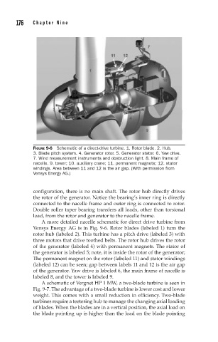
FIGURE 9-6 Schematic of a direct-drive turbine. 1. Rotor blade. 2. Hub.
3. Blade pitch system. 4. Generator rotor. 5. Generator stator. 6. Yaw drive.
7. Wind measurement instruments and obstruction light. 8. Main frame of
nacelle. 9. tower; 10. auxiliary crane; 11. permanent magnets; 12. stator
windings. Area between 11 and 12 is the air gap. (With permission from
Vensys Energy AG.)
configuration, there is no main shaft. The rotor hub directly drives
the rotor of the generator. Notice the bearing’s inner ring is directly
connected to the nacelle frame and outer ring is connected to rotor.
Double roller taper bearing transfers all loads, other than torsional
load, from the rotor and generator to the nacelle frame.
A more detailed nacelle schematic for direct drive turbine from
Vensys Energy AG is in Fig. 9-6. Rotor blades (labeled 1) turn the
rotor hub (labeled 2). This turbine has a pitch drive (labeled 3) with
three motors that drive toothed belts. The rotor hub drives the rotor
of the generator (labeled 4) with permanent magnets. The stator of
the generator is labeled 5; note, it is inside the rotor of the generator;
The permanent magnet on the rotor (labeled 11) and stator windings
(labeled 12) can be seen; gap between labels 11 and 12 is the air gap
of the generator. Yaw drive is labeled 6, the main frame of nacelle is
labeled 8, and the tower is labeled 9.
A schematic of Vergnet HP 1 MW, a two-blade turbine is seen in
Fig. 9-7. The advantage of a two-blade turbine is lower cost and lower
weight. This comes with a small reduction in efficiency. Two-blade
turbines require a teetering hub to manage the changing axial loading
of blades. When the blades are in a vertical position, the axial load on
the blade pointing up is higher than the load on the blade pointing