
Page 209 - Fluid Power Engineering
P. 209
W i nd T urbine Generator (WTG) Components 181
Lifting beam
Downwind
nacelle
Lifting cables
Upwind nacelle
+ Rotor
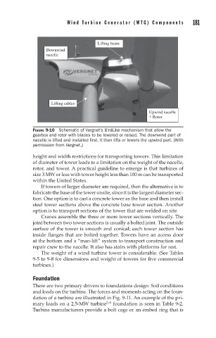
FIGURE 9-10 Schematic of Vergnet’s BirdLike mechanism that allow the
gearbox and rotor with blades to be lowered or raised. The downwind part of
nacelle is lifted and installed first. It then lifts or lowers the upwind part. (With
permission from Vergnet.)
height and width restrictions for transporting towers. This limitation
of diameter of tower leads to a limitation on the weight of the nacelle,
rotor, and tower. A practical guideline to emerge is that turbines of
size 3 MW or less with tower height less than 100 m can be transported
within the United States.
If towers of larger diameter are required, then the alternative is to
fabricatethebaseofthetoweronsite,sinceitisthelargestdiametersec-
tion. One option is to cast a concrete tower as the base and then install
steel tower sections above the concrete base tower section. Another
option is to transport sections of the tower that are welded on site.
Cranes assemble the three or more tower sections vertically. The
joint between two tower sections is usually a bolted joint. The outside
surface of the tower is smooth and conical; each tower section has
inside flanges that are bolted together. Towers have an access door
at the bottom and a “man-lift” system to transport construction and
repair crew to the nacelle. It also has stairs with platforms for rest.
The weight of a wind turbine tower is considerable. (See Tables
9-5 to 9-8 for dimensions and weight of towers for five commercial
turbines.)
Foundation
There are two primary drivers to foundations design: Soil conditions
and loads on the turbine. The forces and moments acting on the foun-
dation of a turbine are illustrated in Fig. 9-11. An example of the pri-
mary loads on a 2.5-MW turbine 5,6 foundation is seen in Table 9-2.
Turbine manufacturers provide a bolt cage or an embed ring that is