
Page 210 - Fluid Power Engineering
P. 210
182 Chapter Nine
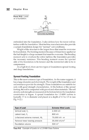
FIGURE 9-11 Loads M y
on a foundation.
M z
F y
F x
Soil
Concrete foundation
embedded into the foundation. It also defines how the tower will in-
terface with the foundation. Most turbine manufacturers also provide
a sample foundation design for “normal” soil conditions.
Weight of the structure is the largest force that must be overcome
by foundation. The bending moment because of thrust force applied at
the hub height is a large moment that must be overcome. The bending
moment acts to overturn the entire turbine; the foundation provides
the necessary resistance. This bending moment causes the upwind
side of the foundation to be tension and the downwind side to be in
compression.
At a high-level, there are two types of foundations spread-footing
and deep foundations.
Spread-Footing Foundation
This is the most common type of foundation. As the name suggests, it
hasalargediameterandshortdepth.Theweightofthefoundationand
soil resistance provide the strength. These foundations are suitable for
soils with good strength characteristics. At the bottom of the spread
footing, the soil is compacted with gravel and other materials. The soil
density and strength are measured at the bottom before the foundation
construction is begun. A spread foundation for 1.5-MW turbine is
typically 17 m in diameter and placed at a depth of 1.5 to 3.5 m (see
Fig. 9-12.)
Type of Load Extreme Wind Loads
Vertical load, F y 2,500 kN
Lateral load, F x 800 kN
Unfactored extreme moment, M z 70,000 kN−m
Factored tower bearing pressure 35,000 kN/m 2
Foundation volume 500 m 3
TABLE 9-2 Example of Loads on a 2.5-MW Class Turbine