
Page 205 - Fluid Power Engineering
P. 205
W i nd T urbine Generator (WTG) Components 177
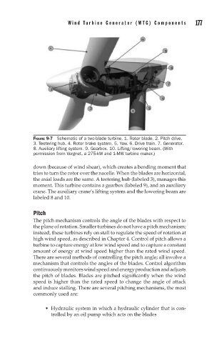
FIGURE 9-7 Schematic of a two-blade turbine. 1. Rotor blade. 2. Pitch drive.
3. Teetering hub. 4. Rotor brake system. 5. Yaw. 6. Drive train. 7. Generator.
8. Auxiliary lifting system. 9. Gearbox. 10. Lifting/lowering beam. (With
permission from Vergnet, a 275-kW and 1-MW turbine maker.)
down (because of wind shear), which creates a bending moment that
tries to turn the rotor over the nacelle. When the blades are horizontal,
the axial loads are the same. A teetering hub (labeled 3), manages this
moment. This turbine contains a gearbox (labeled 9), and an auxiliary
crane. The auxiliary crane’s lifting system and the lowering beam are
labeled 8 and 10.
Pitch
The pitch mechanism controls the angle of the blades with respect to
the plane of rotation. Smaller turbines do not have a pitch mechanism;
instead, these turbines rely on stall to regulate the speed of rotation at
high wind speed, as described in Chapter 4. Control of pitch allows a
turbine to capture energy at low wind speed and to capture a constant
amount of energy at wind speed higher than the rated wind speed.
There are several methods of controlling the pitch angle; all involve a
mechanism that controls the angles of the blades. Control algorithm
continuouslymonitorswindspeedandenergyproductionandadjusts
the pitch of blades. Blades are pitched significantly when the wind
speed is higher than the rated speed to change the angle of attack
and induce stalling. There are several pitching mechanisms, the most
commonly used are:
Hydraulic system in which a hydraulic cylinder that is con-
trolled by an oil pump which acts on the blades