
Page 207 - Fluid Power Engineering
P. 207
W i nd T urbine Generator (WTG) Components 179
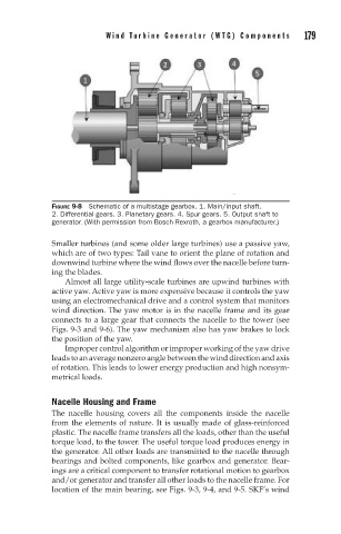
FIGURE 9-8 Schematic of a multistage gearbox. 1. Main/input shaft.
2. Differential gears. 3. Planetary gears. 4. Spur gears. 5. Output shaft to
generator. (With permission from Bosch Rexroth, a gearbox manufacturer.)
Smaller turbines (and some older large turbines) use a passive yaw,
which are of two types: Tail vane to orient the plane of rotation and
downwind turbine where the wind flows over the nacelle before turn-
ing the blades.
Almost all large utility-scale turbines are upwind turbines with
active yaw. Active yaw is more expensive because it controls the yaw
using an electromechanical drive and a control system that monitors
wind direction. The yaw motor is in the nacelle frame and its gear
connects to a large gear that connects the nacelle to the tower (see
Figs. 9-3 and 9-6). The yaw mechanism also has yaw brakes to lock
the position of the yaw.
Improper control algorithm or improper working of the yaw drive
leads to an average nonzero angle between the wind direction and axis
of rotation. This leads to lower energy production and high nonsym-
metrical loads.
Nacelle Housing and Frame
The nacelle housing covers all the components inside the nacelle
from the elements of nature. It is usually made of glass-reinforced
plastic. The nacelle frame transfers all the loads, other than the useful
torque load, to the tower. The useful torque load produces energy in
the generator. All other loads are transmitted to the nacelle through
bearings and bolted components, like gearbox and generator. Bear-
ings are a critical component to transfer rotational motion to gearbox
and/or generator and transfer all other loads to the nacelle frame. For
location of the main bearing, see Figs. 9-3, 9-4, and 9-5. SKF’s wind