
Page 212 - Fluid Power Engineering
P. 212
184 Chapter Nine
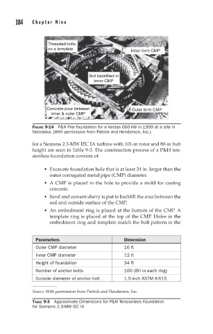
Threaded bolts
on a template Inner form CMP
Soil backfilled in
inner CMP
Concrete pour between Outer form CMP
inner & outer CMP
FIGURE 9-14 P&H Pier foundation for a Vestas 660-kW in 1999 at a site in
Nebraska. (With permission from Patrick and Henderson, Inc.)
for a Siemens 2.3-MW IEC IA turbine with 101-m rotor and 80-m hub
height are seen in Table 9-3. The construction process of a P&H ten-
sionless foundation consists of:
Excavate foundation hole that is at least 24 in. larger than the
outer corrugated metal pipe (CMP) diameter.
A CMP is placed in the hole to provide a mold for casting
concrete.
Sand and cement slurry is put to backfill the area between the
soil and outside surface of the CMP.
An embedment ring is placed at the bottom of the CMP. A
template ring is placed at the top of the CMP. Holes in the
embedment ring and template match the bolt pattern in the
Parameters Dimension
Outer CMP diameter 16 ft
Inner CMP diameter 12 ft
Height of foundation 34 ft
Number of anchor bolts 160 (80 in each ring)
Outside diameter of anchor bolt 1.5-inch ASTM A-615
Source: With permission from Patrick and Henderson, Inc.
TABLE 9-3 Approximate Dimensions for P&H Tensionless Foundation
for Siemens 2.3-MW IEC IA