
Page 268 - Fluid Power Engineering
P. 268
Deploying W i nd T urbines in Grid 235
WTG WTG WTG
System System System
MV to HV
Transformer CB
CB CB Feeder-subfeeder
CB
WTG WTG WTG
System System System
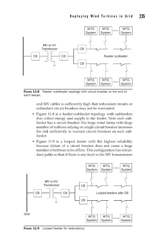
FIGURE 11-8 Feeder–subfeeder topology with circuit breaker at the end of
each feeder.
and MV cables is sufficiently high that redundant circuits or
redundant circuit breakers may not be warranted.
Figure 11-8 is a feeder–subfeeder topology with subfeeders
that collect energy and supply to the feeder. Note each sub-
feeder has a circuit breaker. For large wind farms with large
number of turbines relying on single circuit breaker increases
the risk sufficiently to warrant circuit breakers on each sub-
feeder.
Figure 11-9 is a looped feeder with the highest reliability
because failure of a circuit breaker does not cause a large
number of turbines to be offline. This configuration has redun-
dant paths so that if there is any fault in the MV transmission
WTG WTG WTG
System System System
MV to HV
Transformer CB
CB CB Looped feeders with CB
CB
Grid
WTG WTG WTG
System System System
FIGURE 11-9 Looped feeder for redundancy.