
Page 263 - Fluid Power Engineering
P. 263
230 Chapter Eleven
the power factor is 70%, although the generators, transmission, and
other components are running at full capacity (10 MVA), the system
is delivering only 7 MW of real power; the rest is reactive power or
“wattless power” that performs no work. All the components are at
full capacity or fully loaded in this system because the maximum
amount of current is flowing through the system causing losses of
2
i R t with an appropriate amount of temperature rise. In this situation,
despite current flow at full capacity, only 70% of real power that is
expected at the consumption point is, in fact, delivered. Suppose a
load in this system requires 9.5 MW of real power. In order to satisfy
this load, 9.5/0.7 = 13.5 MVA of total apparent power is required. This
will overload the 10 MVA system. The solution to low power factor
is to install VAR compensators at appropriate points in the system in
order to deliver higher amount of power to loads.
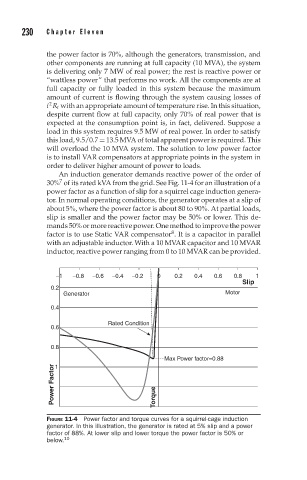
An induction generator demands reactive power of the order of
7
30% of its rated kVA from the grid. See Fig. 11-4 for an illustration of a
power factor as a function of slip for a squirrel cage induction genera-
tor. In normal operating conditions, the generator operates at a slip of
about 5%, where the power factor is about 80 to 90%. At partial loads,
slip is smaller and the power factor may be 50% or lower. This de-
mands50%ormorereactivepower.Onemethodtoimprovethepower
8
factor is to use Static VAR compensator . It is a capacitor in parallel
with an adjustable inductor. With a 10 MVAR capacitor and 10 MVAR
inductor, reactive power ranging from 0 to 10 MVAR can be provided.
−1 −0.8 −0.6 −0.4 −0.2 0 0.2 0.4 0.6 0.8 1
Slip
0.2
Generator Motor
0.4
Rated Condition
0.6
0.8
Max Power factor=0.88
Power Factor Torque
1
FIGURE 11-4 Power factor and torque curves for a squirrel-cage induction
generator. In this illustration, the generator is rated at 5% slip and a power
factor of 88%. At lower slip and lower torque the power factor is 50% or
below. 10