
Page 258 - Fluid Power Engineering
P. 258
Deploying W i nd T urbines in Grid 225
FIGURE 11-1
Symbols used in a
single-line diagram. Generator Fuse
Oil/Liquid
Ground
Circuit Breaker
Voltage Air Circuit
Transformer Breaker
Current
Meter
Transformer
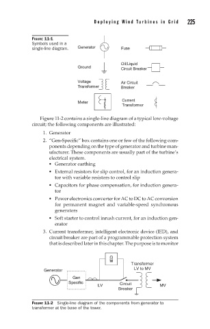
Figure 11-2 contains a single-line diagram of a typical low-voltage
circuit; the following components are illustrated:
1. Generator
2. “Gen-Specific” box contains one or few of the following com-
ponents depending on the type of generator and turbine man-
ufacturer. These components are usually part of the turbine’s
electrical system.
Generator earthing
External resistors for slip control, for an induction genera-
tor with variable resistors to control slip
Capacitors for phase compensation, for induction genera-
tor
Power electronics converter for AC to DC to AC conversion
for permanent magnet and variable-speed synchronous
generators
Soft starter to control inrush current, for an induction gen-
erator
3. Current transformer, intelligent electronic device (IED), and
circuit breaker are part of a programmable protection system
thatisdescribedlaterinthischapter.Thepurposeistomonitor
IED
Transformer
LV to MV
Generator
Gen
Specific Circuit
LV MV
Breaker
FIGURE 11-2 Single-line diagram of the components from generator to
transformer at the base of the tower.