
Page 262 - Fluid Power Engineering
P. 262
Deploying W i nd T urbines in Grid 229
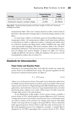
Power-Carrying Power
Voltage Capacity Length
Secondary network, low voltage 200 kW 34 kW-km
Distribution network, medium voltage 10 MW 85 MW-km
2
TABLE 11-3 Power-Carrying Capacity and Power Length of 150 mm Aluminum
Underground Cable
transmission lines. The exact criteria depend on the current load on
the lines—the amount of energy that is currently being carried on the
lines.
In most cases, within a wind farm, power is transmitted using un-
derground cables. All transmission within wind farm from turbines
to substation is called a collection system. Underground cables used
in collection systems are three-phase cables bundled into one cable
with appropriate shielding. The most common cable is the 150-mm 2
6
aluminum conductor. The amount of power it can transmit as a func-
tion of voltage and “power length” is shown in Table 11-3. Power
length divided by the power yields the distance that power can be
transmitted to yield a loss of under 5%.
Standards for Interconnection
Power Factor and Reactive Power
Inductance on transmission lines and inductive loads can cause the
power factor to be different from unity. The general equation for the
real power carried in three-phase AC lines is:
√
P = 3Vi cos ϕ (11-2)
where cos ϕ is the power factor. The goal of any electricity network is
to obtain a power factor that is as close to unity as possible. The causes
of poor power factor are: Magnetizing loads like transformers, motors,
generators, and induction furnaces; long transmission lines; inverter
producing poor current wave form. These types of loads cause the
voltage and current to be out of phase.
As an illustration of the impact of low power factor, consider a
power factor of 70%, which implies a phase difference of 45 between
◦
voltage and current. Generators, transmission lines, and transformers
are rated in terms of the product of voltage and current with units
of kilo-volt-amps (kVA) or mega-volt-amps (MVA). This is called the
total apparent power. Power factor is also the ratio of real power to
the total apparent power. For simplicity, consider a system that is
designed for 10 MVA operating with a power factor is 70%. When