
Page 174 - Wind Energy Handbook
P. 174
148 AERODYNAMICS OF HORIZONTAL-AXIS WIND TURBINES
800 ESBJERG measurements
Blade root bending moment (kNm) 750 Equilibrium wake
Dynamic wake
700
650
600
550
500
450
400
350
0 10 20 30 40 50
Time (seconds)
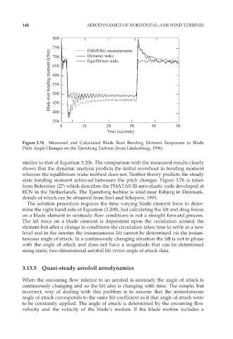
Figure 3.76 Measured and Calculated Blade Root Bending Moment Responses to Blade
Pitch Angle Changes on the Tjæreborg Turbine (from Lindenburg, 1996).
similar to that of Equation 3.206. The comparison with the measured results clearly
shows that the dynamic analysis predicts the initial overshoot in bending moment
whereas the equilibrium wake method does not. Neither theory predicts the steady
state bending moment achieved betweeen the pitch changes. Figure 3.76 is taken
from Reference (27) which describes the PHATAS III aero-elastic code developed at
ECN in the Netherlands. The Tjæreborg turbine is sited near Esbjerg in Denmark,
details of which can be obtained from Snel and Schepers, 1995.
The solution procedure requires the time varying blade element force to deter-
mine the right-hand side of Equation (3.208), but calculating the lift and drag forces
on a blade element in unsteady flow conditions is not a straight forward process.
The lift force on a blade element is dependent upon the circulation around the
element but after a change in conditions the circulation takes time to settle at a new
level and in the interim the instantaneous lift cannot be determined via the instan-
taneous angle of attack. In a continuously changing situation the lift is not in phase
with the angle of attack and does not have a magnitude that can be determined
using static, two-dimensional aerofoil lift versus angle of attack data.
3.13.5 Quasi-steady aerofoil aerodynamics
When the oncoming flow relative to an aerofoil is unsteady the angle of attack is
continuously changing and so the lift also is changing with time. The simple, but
incorrect, way of dealing with this problem is to assume that the instantaneous
angle of attack corresponds to the same lift coefficient as if that angle of attack were
to be constantly applied. The angle of attack is determined by the oncoming flow
velocity and the velocity of the blade’s motion. If the blade motion includes a