
Page 178 - Wind Energy Handbook
P. 178
152 AERODYNAMICS OF HORIZONTAL-AXIS WIND TURBINES
1
Lc(τ)
0.5
Lc(ω)
0
0 10 20 30 40 50
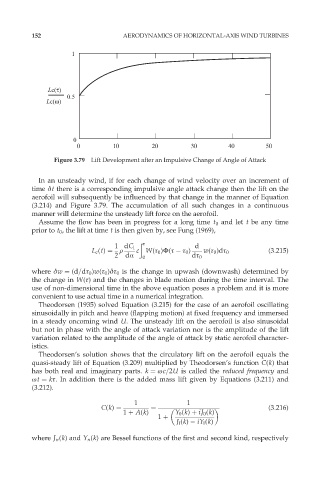
Figure 3.79 Lift Development after an Impulsive Change of Angle of Attack
In an unsteady wind, if for each change of wind velocity over an increment of
time ät there is a corresponding impulsive angle attack change then the lift on the
aerofoil will subsequently be influenced by that change in the manner of Equation
(3.214) and Figure 3.79. The accumulation of all such changes in a continuous
manner will determine the unsteady lift force on the aerofoil.
Assume the flow has been in progress for a long time t 0 and let t be any time
prior to t 0 , the lift at time t is then given by, see Fung (1969),
ð ô
1 dC l d
L c (t) ¼ r c W(ô 0 )Ö(ô ô 0 ) w(ô 0 )dô 0 (3:215)
2 dÆ 0 dô 0
where äw ¼ (d=dô 0 )w(ô 0 )äô 0 is the change in upwash (downwash) determined by
the change in W(ô) and the changes in blade motion during the time interval. The
use of non-dimensional time in the above equation poses a problem and it is more
convenient to use actual time in a numerical integration.
Theodorsen (1935) solved Equation (3.215) for the case of an aerofoil oscillating
sinusoidally in pitch and heave (flapping motion) at fixed frequency and immersed
in a steady oncoming wind U. The unsteady lift on the aerofoil is also sinusoidal
but not in phase with the angle of attack variation nor is the amplitude of the lift
variation related to the amplitude of the angle of attack by static aerofoil character-
istics.
Theodorsen’s solution shows that the circulatory lift on the aerofoil equals the
quasi-steady lift of Equation (3.209) multiplied by Theodorsen’s function C(k) that
has both real and imaginary parts. k ¼ øc=2U is called the reduced frequency and
øt ¼ kô. In addition there is the added mass lift given by Equations (3.211) and
(3.212).
1 1
C(k) ¼ ¼ (3:216)
1 þ A(k) Y 0 (k) þ iJ 0 (k)
1 þ
J l (k) iY l (k)
where J n (k) and Y n (k) are Bessel functions of the first and second kind, respectively