
Page 175 - Wind Energy Handbook
P. 175
UNSTEADY FLOW – DYNAMIC INFLOW 149
torsional (pitching) component then the angle of attack will vary along the chord
length: thin aerofoil theory (see Anderson, 1991) shows that the point 3=4 of the
chord length from the leading edge is where the angle of attack must be deter-
mined.
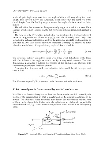
The velocities that determine the quasi-steady angle of attack for a rotor blade
element are shown in Figure 3.77, the dot represents differentiation with respect to
time t.
The flow velocity W(t), which includes the rotational speed of the blade element,
varies in magnitude and direction (Æ W (t)) with the unsteady wind. W(t) also
includes the induced velocities caused by the rotor disc as might be determined by
Equation (3.208). The elastic deflection velocities (subscript e) caused by blade
vibration also influence the quasi-steady angle of attack, which is
@â e 3 1
Æ(t) ¼ Æ W (t) v e (t) h c (3:209)
@t 4 W(t)
The structural velocity caused by chord-wise (edge-wise) deflections of the blade
will also influence the angle of attack but by a very small amount. The non-
dimensional parameter h defines the position of the pitching axis (flexural axis,
shear centre position) of the blade element.
Assuming the structural deflection velocities to be small the lift force per unit
span is then
1 2 dC l
L c (t) ¼ rW(t) c sin Æ(t) (3:210)
2 dÆ
The lift-curve slope dC l =dÆ is assumed to be the same as for the static case.
3.14.6 Aerodynamic forces caused by aerofoil acceleration
In addition to the circulatory forces there are forces on the aerofoil caused by the
inertia of the surrounding air that is accelerated as the aerofoil accelerates in its
motion. The additional terms are added mass forces. The added mass per unit span
of blade can be shown to be that of a circular cylinder of air of diameter equal to the
2
aerofoil chord (ðc =4)r. There are two components to the added mass force (Fung,
1969).
v (t) v (t) - β (t)(3/4-h)c
e
e
e
Pitch
β (t) axis
e
u (t)
e
h c 3/4 c 3/4 chord point
α (t)
W
W(t)
Figure 3.77 Unsteady Flow and Structural Velocities Adjacent to a Rotor Blade