
Page 263 - Wind Energy Handbook
P. 263
BLADE LOADS DURING OPERATION 237
350
Out-of-plane moment for U = 20 m/s & x/D = 1
Aerodynamic out-of-plane root bending moment (kNm) 250 Out-of-plane moment for U = 10 m/s x/D=1.5
300
200
Rotor diameter = 40 m
Rotational speed = 30 rpm
x/D=1
150
x = distance between rotor plane and tower centreline
100
D = tower diameter = 2 metre
50
0 NB: Dynamic effects due to blade flexibility omitted
90 100 110 120 130 140 150 160 170 180 190 200 210
Azimuth (degrees)
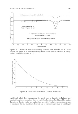
Figure 5.14 Variation of Blade Root Bending Moments with Azimuth due to Tower
Shadow, for Typical 40 m Diameter Stall-regulated Upwind Machine Operating in Steady,
Uniform Winds of 10 m=s and 20 m=s
140
Edgewise bending moment due to gravity - horizontal blade (kNm) 100
120
80
60
40
20
0
0 2 4 6 8 10 12 14 16 18 20
Radius (m)
Figure 5.15 Blade ‘TR’ Gravity Bending Moment Distribution
centrifugal relief. The phenomenon is non-linear, so iterative techniques are
required to arrive at a solution. Greater centrifugal relief can be obtained by coning
the rotor so that the blades are inclined downwind in the first place. A balance can
be struck so that the maximum forward out-of-plane moment due to centrifugal