
Page 262 - Wind Energy Handbook
P. 262
236 DESIGN LOADS FOR HORIZONTAL-AXIS WIND TURBINES
0.5
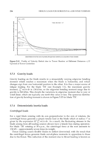
x/D = 0.75 Tower diameter = D
Velocity deficit as a proportion of undisturbed wind speed 0.3 x/D = 1.25
0.4
x/D = 1
0.2
0.1
x/D = 1.5
-0.1 0 0 x/D = 2 0.5 1 1.5 2 2.5 3 3.5
Lateral distance from flow axis of symmetry through tower centreline, as a proportion of tower diameter
Figure 5.13 Profile of Velocity Deficit due to Tower Shadow at Different Distances x=D
Upwind of Tower Centreline
5.7.3 Gravity loads
Gravity loading on the blade results in a sinusoidally varying edgewise bending
moment which reaches a maximum when the blade is horizontal, and which
changes sign from one horizontal position to the other. It is thus a major source of
fatigue loading. For the blade ‘TR’ (see Example 5.1), the maximum gravity
Ð
R
moment, m(r)r dr is 134 kNm, so the edgewise bending moment range due to
0
gravity is 268 kNm. This dwarfs the variations in edgewise moment due to yaw or
wind shear, which are typically one tenth this value or less. The spanwise distribu-
tion of gravity bending moment is shown in Figure 5.15 for blade ‘TR’.
5.7.4 Deterministic inertia loads
Centrifugal loads
For a rigid blade rotating with its axis perpendicular to the axis of rotation, the
centrifugal forces generate a simple tensile load in the blade which at radius r is
Ð
given by the expression Ù 2 R m(r)r dr. As a result, the fluctuating stresses in the
r
blade arising from all loading sources always have a tensile bias during operation.
For blade ‘TR’ rotating at 30 r:p:m:, the centrifugal force at the root amounts to
134 kN – approximately seven times its weight.
Thrust loading causes flexible blades to deflect downwind, with the result that
the centrifugal forces generate blade out-of-plane moments in opposition to those
due to the thrust. This reduction of the moment due to thrust loading is known as